Confined Masonry Construction
Confined masonry is a technique for constructing a building in an earthquake-prone region. In confined masonry construction, the masonry walls are reinforced with vertical and horizontal reinforcement bars, typically made of steel, and are encased within concrete columns or beams. Concrete confinement helps improve the overall strength and ductility of the masonry walls, making them more resistant to seismic forces.
Unlike frame structure, it is limited to the construction of 2 story building only. However, in Mexico, 6-storey confined masonry buildings (Mexico | Confined Masonry Network, 2013) are constructed and 4-storey buildings are constructed with CM system in Chile.
Components of Confined Masonry
It is important to know the components of confined masonry structures while designing or constructing a building in a seismic active area. The structural components of a confined masonry building are:
1. Masonry Walls
Confined masonry walls serve a crucial role in structural integrity, efficiently transferring the weight of the structure’s upper floors to the foundation while also serving as sturdy bracing panels that withstand lateral seismic forces. A toothed edge/interface should be provided on either side of the masonry wall. It is also recommended to provide horizontal dowel bars between the wall and column interface. These will interlock concrete tie columns and masonry walls improving their resilience during earthquakes, thereby ensuring the overall stability and safety of the building.
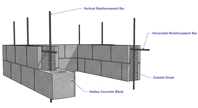
The minimum thickness of the wall is usually 100 mm and the ratio of height to thickness should not exceed 30. Confined masonry walls can be constructed using various masonry units. Popular masonry units are hollow blocks made of concrete or clay. Burnt clay bricks are also used as masonry units. Hollow block masonry units are provided with vertical reinforcement bars which are subsequently grouted with a cement base grout to protect the reinforcement from corrosion.
Horizontal reinforcement is provided in the form of ladder reinforcement (placed in horizontal joints) or deformed reinforcement bars placed in bond beams typically located at the lintel level (similar to RC lintel bands in Indian masonry construction). In general, the reinforcement is distributed uniformly along the wall length and height.
2. Confining Elements
The confining elements provide confinement to the structure. They are similar to columns and beams in the frame structure and are known as tie columns and tie beams. They resist gravity loads and ensure the vertical stability of a building in an earthquake. They provide restraint to masonry walls and protect them from complete disintegration even in major earthquakes.
- Tie Columns:
The width of the tie column should not be less than the width of the wall. The cross-sectional dimension of the tie column recommended by the guideline is 100 mm by 100 mm. The reinforcement for the tie columns should start from the foundation. Therefore, reinforcement cages containing 4 number of vertical bars and cross-ties should be assembled and placed at the designated column location.
There should be at least 4 number of deformed bars as longitudinal reinforcement. The cross-tie should be at least 8 mm in diameter with 135° hooks. Most of the building code specifies spacing of cross ties between 100 to 200 mm.
Splicing of longitudinal reinforcement is not permitted on the ground floor by the code book even for the confined masonry structure. The splicing should be conducted only at the mid-length of the column at a minimum length of 500 mm or the development length of the reinforcement bar.
Concrete is poured into tie columns once the desired height of the masonry wall is achieved, typically recommended at a height of 1.2 meters to ensure proper compaction.
The location of tie columns also plays a crucial role in confining the building. Therefore, the tie column should be placed at the following location:
- at wall-to-wall intersection;
- additional tie columns can be added within the wall if needed to maintain a maximum spacing of 4 meters between adjacent confining elements;
- at the free end of a wall, and
- at the end of the wall opening for door and window
- Tie Beams:
Tie beams have a very important role in confined masonry construction since they help confine the masonry walls. Thus, they are constructed on top of the walls at each floor level and their vertical spacing is not more than 3 m. The cross-sectional dimensions of the tie beam should not be less than 100 mm by 100 mm or the width of the beam is equal to the width of the wall.
Tie beams are provided with 4 numbers of longitudinal bars with equally spaced stirrups. The size of the longitudinal bars should not be less than 10 mm in diameter and their lap length should not be less than 500 mm according to the Indian Confined masonry construction guideline.
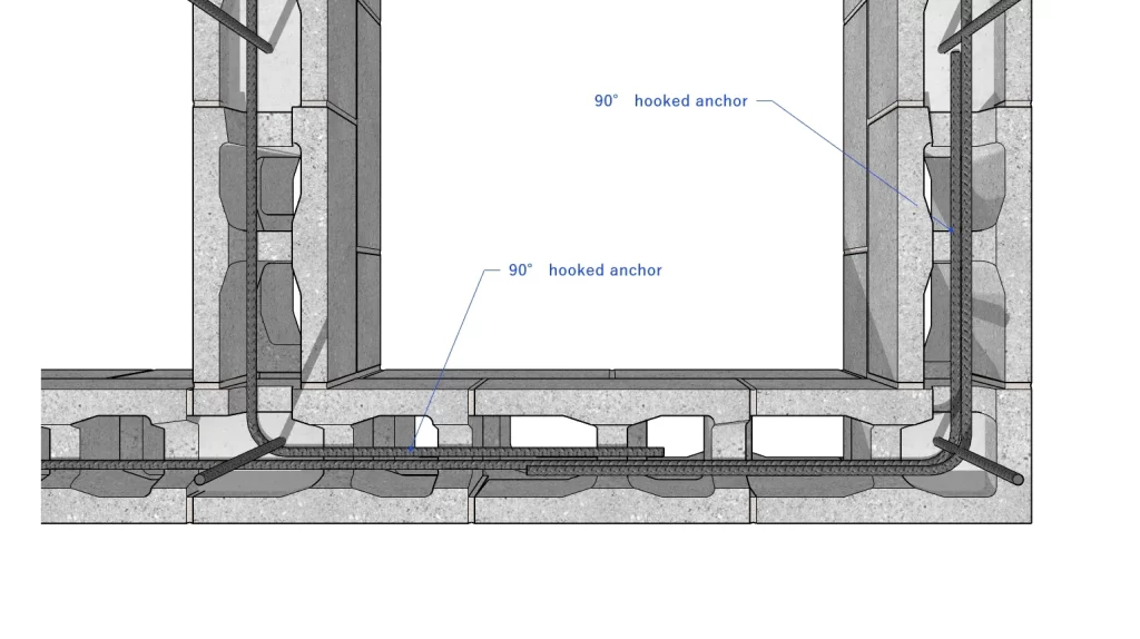
The longitudinal bars are provided with the 90° hooked anchorage at the beam intersection, to ensure the effectiveness of tie beams in resisting earthquake loads. The hook length should not be less than 500 mm or the development length of the longitudinal bars.
- Lintel Beam
Lintel beams are provided across the larger openings. They are integrated with tie beams at all the floor levels. Additional reinforcement bars are provided in the lintel beam.
3. Floor and Roof slabs
Floor and roof slabs become integral parts of the confined masonry structure if constructed monolithically with band and tie beams. The reinforcement of floor slabs should intertwine with the tie beam.
4. Plinth Band
Plinth bands are horizontal concrete elements that are typically placed between the plinth masonry wall and at the bottom of the masonry walls. This helps to transmit the wall load to the foundation and also protects the ground floor walls from excessive settlement in soft soil conditions.
The reinforcement of the plinth band is provided similar to tie beams.
Also, read: Plinth Beam: Enhancing Building Stability.
5. Foundation
Usually, a traditional strip foundation is constructed with masonry units that may include stone, bricks and concrete blocks. The depth of the typical foundation varies between 400 mm to 1000 mm. The width of the foundation should not be less than the width of the masonry wall above. However, the minimum width of the foundation is usually 400 mm. A typical masonry wall foundation is shown in the figure below.
On a well-compacted and levelled ground, lean concrete is laid, over which a masonry foundation is constructed. The reinforcement is not mandatory provided. However, if the ground condition is not stable or soft, the longitudinal reinforcement and distribution bars spaced equally may be provided along the length and across the strip foundation respectively.
Also, read: 4 Types of Seismic Bands for Masonry Structure
FAQs:
Q: Can AAC block be used in Confined Masonry Construction?
Answer: Yes, AAC blocks can be used as an alternative to concrete hollow blocks for confined masonry construction due to their properties of durability and lightweight. The light weight of the AAC block can be advantageous as it can contribute to significant weight loss of the CM building.
Q: What type of Concrete block should be used for Confined masonry Construction?
Answer: The hollow concrete brick with two holes should not be used as it is not strong enough to withstand the load above. Therefore, three or four-hole hollow concrete blocks should be used for the confined masonry construction.
References:
- Murty, C.V.R. (). What is a Confined Masonry Construction? Learning Earthquake Design and Construction. IIT Jodhpur. https://www.bmtpc.org/DataFiles/CMS/file/EQTIPS_PDFFiles/EQTip28.pdf
- Thakur, A., & Senthil, K. (2024). Influential parameters on the seismic performance of confined masonry – a comprehensive review. Journal of Building Pathology and Rehabilitation, 9(1). https://doi.org/10.1007/s41024-024-00414-6