California Bearing Ratio (CBR) is a crucial parameter in geotechnical engineering used to evaluate the mechanical strength and load-bearing capacity of soil. Developed by the California Division of Highways in the early 1930s, CBR has become a standard test method globally for assessing the suitability of soils for road construction and other infrastructure projects. This article explores the significance of CBR, its testing procedure, and its applications in civil engineering.
The strength of the subgrade is an important factor in determining the necessary thickness of a flexible pavement. The outcomes derived from CBR tests are employed alongside empirical curves, drawn from practical experience, to formulate designs for flexible pavements.
While the test outcome may seem somewhat arbitrary, providing an empirical percentage value, it might not directly align with the fundamental properties governing soil shear strength, like cohesion and the angle of internal friction. However, recent efforts have focused on establishing connections between CBR values and soil-bearing capacity, along with its plasticity index.
Definition
The California Bearing Ratio (CBR) is described as the ratio of the force per unit area needed to penetrate a soil mass using a standard circular plunger with a diameter of 50 mm, at a consistent rate of 1.25 mm/min, to that needed for an equivalent penetration of a standard material.
Understanding the CBR
The standard material is crushed stone and the load which has been obtained from a test on it is the standard load, this material is considered to have a CBR of 100%.
CBR values are typically determined for penetrations of 2.5 mm and 5 mm. If the ratio at 5 mm consistently surpasses that at 2.5 mm, the 5 mm value is preferred. Otherwise, the more common 2.5 mm value is used.
The CBR test is commonly conducted in the laboratory, either on undisturbed samples or remoulded samples, depending on the anticipated condition of the subgrade soil in actual use. It is essential to replicate in the laboratory the pressure and moisture conditions expected in the field to ensure accurate testing.
Determination of California Bearing Ratio
Laboratory Determination of CBR
The apparatus consists of a cylindrical mould of 150 mm inside diameter and 175 mm in height. It is provided with a detachable metal extension collar 50 mm in height and a detachable perforated base plate 10 mm thick. A circular metal spacer disc 148 mm in diameter and 47.7 mm in height is also provided. A handle for screwing into the disc to facilitate its removal is also available. A standard metal rammer (IS: 9198-1979) is used for compaction for preparing remoulded specimens. The apparatus is shown in figure below.

One annular metal weight and several slotted weights weighing 24.5 N (2.5 kg) each (147 mm in diameter with a central hole 53 mm in diameter) are used for providing the necessary surcharge pressure.
A metal penetration plunger, 50 mm in diameter and not less than 100 mm long, is used for penetrating the specimen in the mould. If it is necessary to use a plunger of greater length, a suitable extension rod may be used. Dial gauges reading to 0.01 mm are used to record the penetration.
I.S. Sieves (20 mm and 4.75 mm), and other general apparatus such as a mixing bowl, straight edge, scales, soaking tank or pan, drying oven, filter paper, dishes and a calibrated measuring jar are also required.
A loading machine of capacity 50 kN (5,000 kg approx.) in which the rate of displacement of 1.25 mm/min can be maintained is necessary.
Preparation of Test Specimen
The test may be performed on undisturbed specimens or on remoulded specimens which may be compacted either statically or dynamically.
Undisturbed specimens shall be obtained by fitting to the mould, the steel cutting edge of 150 mm internal diameter and pushing the mould as gently as possible into the ground. When the mould is sufficiently full of soil, it shall be removed by underdigging. The top and bottom undersurfaces are then trimmed to give the desired length to the specimen.
If the specimen is loose in the mould, the annular cavity shall be filled with paraffin wax thus ensuring that the soil receives proper support from the sides of the mould during the penetration test. The density of the soil and the water content of the soil must be determined by one of the available standard methods.
Remoulded specimens must be prepared in such a way that the dry density and water content correspond to those values at which the CBR value is desired. The material shall pass a 20-mm IS sieve. Allowance for larger material shall be made by replacing it with an equal amount of material which passes a 20 mm IS sieve but is retained on a 4.75 mm IS Sieve.
Statically compacted specimens may be obtained by placing the calculated mass of soil in the mould and pressing in the displacer disc, a filter paper is placed between the disc and the soil. The pressing may be stopped when the top of the displacer disc is flush with the rim of the mould.
Dynamically compacted specimens may be obtained by using the standard metal rammer in accordance with ‘‘IS: 2720 (Part VII)—1983—Determination of water content—dry density relation using light compaction’’ or ‘‘IS: 2720 (Part VIII)-1983—Determination of water content— dry density relation using heavy compaction’’. The mould with the extension collar attached shall be clamped to the base plate. The spacer disc shall be inserted over the base plate and a disc of coarse filter paper placed on the top of the spacer disc. After compacting the soil into the mould, the extension collar shall be removed and the top of the sample struck off level with the rim of the mould by means of a straight edge.
The perforated base plate and spacer disc shall be removed to record the mass of the mould and the compacted soil. A disc of coarse filter paper shall be placed on the perforated base plate, the mould and the compacted soil shall be
inverted, and the perforated base plate clamped to the mould with the compacted soil in contact with the filter paper.
In both cases of compaction, if soaking of the sample is required, representative samples of the material shall be taken both before compaction and after compaction for determination of water content.
If the sample is not to be soaked, a representative sample of the material after the penetration shall be taken for the determination of the water content.
Test Procedure
- The mould containing the specimen and the base plate is positioned on the lower plate of the loading machine.
- Surcharge weights are added to create a pressure equivalent to the combined weight of the base material and the pavement. If the specimen has been soaked previously, the surcharge weight matches that used during the soaking period.
- An annular weight is placed above the specimen to prevent soil upheaval into the slots of the weights.
- The plunger is loaded with a force of 39.2 N (4 kg) to ensure full contact with the specimen surface.
- Dial gauges for the proving ring and penetration are zeroed.
- Load application ensures a penetration rate of approximately 1.25 mm/min.
- Load readings are taken at specific penetrations: 0, 0.5, 1.0, 1.5, 2.0, 2.5, 4.0, 5.0, 7.5, 10.0, and 12.5 mm.
- These values are recorded if the maximum load and penetration occur at less than 12.5 mm.
- The plunger is raised and detached from the loading machine.
- Approximately 0.5 N (50 g) of soil is collected from the top 30 mm layer of the specimen for water content determination, following IS: 2720 (Part-II)-1973 standards.
- Verification is conducted for oversized particles, which could affect results if located directly beneath the penetration plunger.

Load-Penetration Curve
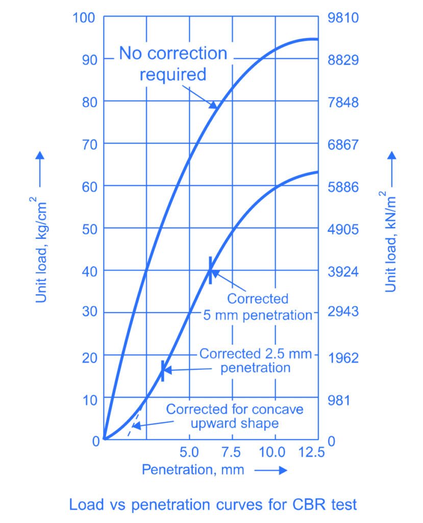
The load vs penetration curve is plotted. Typically, this curve exhibits a predominantly upward convex shape, though the initial segment may appear concave upward due to surface irregularities. To rectify this, a correction is made by drawing a tangent to the upper curve at the point of inflexion.
The corrected curve is derived from this tangent plus the convex segment of the original curve, with the starting point of penetrations shifted to where the tangent intersects the horizontal penetration axis, as depicted in illustrations.
Also, read: WBM Road: Specifications, Construction, Typical and Cross Section
CBR Value
Corresponding to the penetration value at which the CBR is desired, the corrected load shall be taken from the load penetration curve and the CBR can be mathematically expressed as:
\( CBR=\frac P{P_s}\times100 \)
where,
\( P \) = Corrected unit (or total) test load corresponding to the chosen penetration from the load-penetration curve
\( P_s \) = standard unit (or total) load for the same depth of penetration as for PT taken from Table 17.2.
| Depth of Penetration (mm) | Unit standard load | Total standard load | ||
|---|---|---|---|---|
| kg/cm2 | kN/m2 | kg | kN | |
| 2.5 | 70 | 6867 | 1370 | 13.44 |
| 5.0 | 105 | 10300 | 2055 | 20.16 |
| 7.5 | 134 | 13145 | 2630 | 25.80 |
| 10.0 | 162 | 15892 | 3180 | 31.20 |
| 12.5 | 183 | 17952 | 3600 | 35.32 |
Also, read: Geometrics of Hill Road: Effective Design Criteria for Hill Road
Applications of CBR:
- Pavement Design: CBR values play a pivotal role in designing pavement structures by determining the thickness of pavement layers required to withstand anticipated traffic loads. Higher CBR values indicate stronger subgrade soils, necessitating thinner pavement layers.
- Material Selection: CBR values assist engineers in selecting suitable construction materials and optimizing pavement designs based on soil strength characteristics. They help in identifying the need for soil stabilization techniques such as lime or cement treatment to enhance soil strength.
- Quality Control: CBR testing is integral to quality control during construction, ensuring that soil compaction meets specified standards and verifying the suitability of subgrade soils for pavement construction.
- Infrastructure Development: CBR values guide the planning and execution of various infrastructure projects, including highways, airports, embankments, and industrial facilities, by providing critical information on soil behaviour and stability.
Also, read: Embankment Construction: Materials and Specification
References:
- Wikipedia contributors. (2023, June 24). California bearing ratio. Wikipedia. https://en.wikipedia.org/wiki/California_bearing_ratio
- Venkatramaiah, C. (2006). Geotechnical Engineering (3rd ed.). New Age International (P) Limited, Publishers. https://www.newagepublishers.com
- ASTM, 2003e. D1883 Standard Test Method for CBR (California Bearing Ratio) of Laboratory-
- Compacted Soils, Annual Book of ASTM Standards, Vol. 04.02. American Society for Testing
- and Materials, West Conshohocken, PA.
![]()

