A “hill road” refers to a roadway or highway that is constructed and designed on hilly or mountainous terrain. These roads are built to traverse through areas with significant changes in elevation, and they often wind and curve along the contours of the land to make the inclines more manageable for vehicles.
Geometrics of Hill Road
The geometric standard for hill roads is different from those in the plans. The reason behind the difference is the topography of the landmark. Hill roads present unique engineering challenges due to the steep gradients, sharp turns, and potential for adverse weather conditions like heavy rainfall or snowfall. Designing such roads requires careful consideration of various factors to ensure safety and stability for drivers and other road users.
Geometric alignment plays a pivotal role in determining the slope, curvature, and vertical profile of these roads. In this article, we will delve into the essential aspects of geometric alignment and its impact on the construction and safety of hill roads.

Width of Pavement, Roadway and Road Land
The width of pavement, roadway, and road land are critical components in the design and construction of roads, playing a crucial role in ensuring safe and efficient transportation infrastructure. The pavement width refers to the surface layer of the road that directly supports vehicle loads. It is designed to accommodate the expected traffic volume and load-bearing requirements.
The roadway width encompasses the entire driving surface, including the pavement and shoulders, and is influenced by factors such as the number of lanes, traffic flow, and safety considerations.
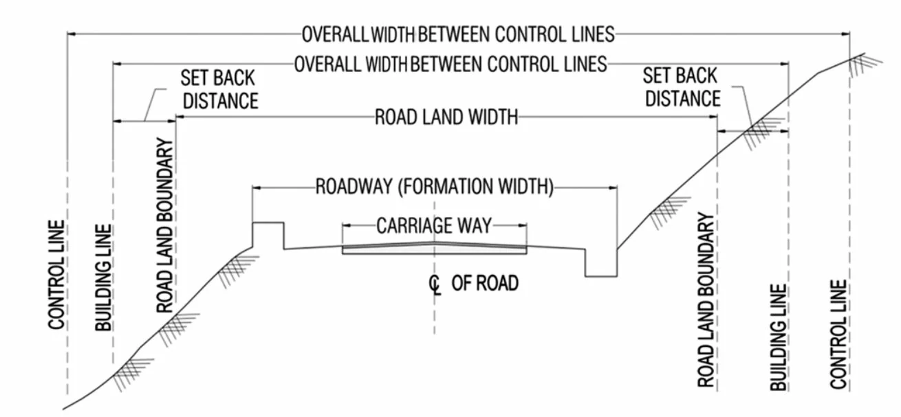
Road land width, also known as the right of way, extends beyond the roadway and includes additional space for safety zones, utilities, and potential future expansions. The dimensions of these elements are carefully determined based on engineering standards, traffic projections, and the specific requirements of the surrounding environment to create a well-balanced and functional road infrastructure. The picture below shows the typical cross-section of road land.

The Table below from the Indian Road Congress provides the recommended width of pavement, roadway and road land (right of way) for different road categories in Hilly Areas with Mountainous and Steep Terrain.
| Road Classification | Pavement Width (m) | Road Width (m) | Right of Way | |
|---|---|---|---|---|
| Normal | Exceptional | |||
| National Highway & Secondary Highway | ||||
| Single Lane | 3.75 | 6.25 | ||
| Two-Lane | 7.00 | 8.8 | 24 | 18 |
| Major District Roads (MDR) | 3.75 | 4.75 | 18 | 15 |
| Other District Roads (ODR) | 3.75 | 4.75 | 15 | 12 |
| Village Roads (VR) | 3.00 | 4.00 | 9 | 9 |
On segments with solid rock foundations, the shoulders can be narrowed by 0.4 m on both sides for two-lane roads and by 0.2 m in alternative situations. The standard minimum setback for building lines beyond the right of way is 50 m in typical cases, but in exceptional circumstances, it can be reduced to 3 m.
Camber or Cross fall
In situations where a hill road exhibits longitudinal gradients surpassing 1 in 20, it is recommended to incorporate a flatter chamber. This adjustment in design helps to ensure smoother transitions and enhanced stability, accommodating the specific challenges posed by the elevated terrain.
| Types of Surface | High-type bituminous surface & CC |
|---|---|
| Subgrade, earth road and shoulder | 3.0 to 4.0 per cent (1 in 33 to 1 in 25) |
| Gravel and WBM surface | 2.5 to 3.0 per cent (1 in 40 to 1 in 33) |
| Bituminous surfaceing | 2.0 to 2.5 per cent (1 in 50 to 1 in 40) |
| High type bituminous surface & CC | 1.7 to 2.0 per cent (1 in 60 to 1 in 50) |
Also, read: Understanding Road Camber: Effects On Vehicle Handling And Road Safety
Sight Distance
The stopping sight distance is calculated from the relation:
\( SSD\;=\;0.278\times Vt\;+\frac{V^2}{254f}\; \)
Wher V = design speed, km/h
t = reaction time, taken as 3 seconds
f = coefficient of friction, assumed as 0.4
Safe stopping sight distances for various speeds given by IRC are given below:
| Speed, Kmph | 20 | 25 | 30 | 40 | 50 |
| SSD, m | 20 | 30 | 35 | 50 | 70 |
The overtaking sight distance is calculated from the relation:
\( OSD\;=\;0.556\times Vb\;+\;2s\;+\;0.278\times TV\;b\;+\;0.278\times VT \)
V= speed of overtaking vehicle, km/h
Vb = speed of overtaken Vehicke = (V – 16) km/h
s = spacing of moving vehicles = (0.2Vb +6) m
T = overtaking time
The minimum Overtaking sight distance specified is
| Speed, Kmph | 30 | 40 | 50 |
| OSD, m | 90 | 145 | 210 |
Superelevation
Superelevation, also known as banking or cant, is a geometric design feature applied to road curves to enhance vehicle stability and safety. It involves raising the outer edge of the road surface along a curve to counteract the lateral forces exerted on vehicles during turns. By providing a gradual slope, superelevation reduces the tendency for vehicles to overturn, mitigates the effects of centrifugal forces, and improves overall handling, especially at higher speeds.
The superelevation to be provided at horizontal curves of hill roads is calculated from the formula:

IRC specification that the superelevation should not exceed 7% in the section of hill roads that gets snowbound and 10% in other places.
Superelevation at Culver in Curves:
The wearing course of the culvert’s top surface should have the same cross profile of the approaches. Superelevation can be applied to the abutments while maintaining a consistent thickness for the deck slab as per the design. It is crucial for the top level of the culvert slab to align with the top level of the approaches, preventing any unnecessary jerks when driving on the completed road.
The radii of horizontal curves for different camber rates beyond which superelevation will not be required are as per the table below as given in IRC.
| Design Speed (km/h) | Radii for Chamber of | ||||
|---|---|---|---|---|---|
| 4% | 3% | 2.5% | 2% | 1.7% | |
| 20 | 50 | 60 | 70 | 90 | 100 |
| 25 | 70 | 90 | 110 | 140 | 150 |
| 30 | 100 | 130 | 160 | 200 | 240 |
| 35 | 120 | 180 | 220 | 270 | 320 |
| 40 | 180 | 240 | 280 | 350 | 420 |
| 50 | 280 | 370 | 450 | 550 | 650 |
Also, read: Superelevation In Road Design: Enhancing Safety And Efficiency Of High-Speed Curves
The Radius of Horizontal Curve
The minimum radius of horizontal curves in hill roads, R(min) is calculated from the formula

The lateral friction factor f is taken as 0.15. The minimum radii recommended for various classes of hill roads are given in the Table below from IRC.
| Road Category | Minimum radius meter | |||
|---|---|---|---|---|
| Mountainous terrain | Steep terrain | |||
| not snowbound | not snowbound | not snowbound | not snowbound | |
| N.H & S.H | 50 | 60 | 30 | 33 |
| MDR | 30 | 33 | 14 | 15 |
| ODR | 20 | 23 | 14 | 15 |
| VR | 14 | 15 | 15 | 15 |
Reverse curves are designed to have a minimum radius of 30m for the compound curves and a straight distance of 9 m between their transitional ends. In exceptional cases, the radius can be reduced to 22.5 m and the straight distance is dispensed with.
Widening of Pavement on Curves:
The extra width of the carriageway at horizontal curves is calculated from the relation:
\( W_{\mathit c}\mathit=\frac{\mathit{18}\mathit n}{\mathit R}\mathit+\frac{\mathit0\mathit.\mathit1\mathit V}{\sqrt{\mathit R}} \)
where \( n \)is the number of lanes.
The recommended values of extra widening on single and two-lane pavements at curves are below for various speeds.
| The radius of the curve in meter | 14-20 | 20-30 | 30-60 | 60-150 | above 150 |
| The extra width of two-lane road in meter | 1.5 | 1.2 | 0.9 | 0.6 | Nil |
| The radius of the curve in meter | 30-40 | 40-60 | 60-100 | 100-150 | above 150 |
| The extra width of a two-lane road in meter | 1.530-40 | 1.2 | 0.9 | 0.6 | Nil |
The development of roadways should be augmented, particularly at horizontal curves. On single-lane National and State highways, the additional width of the roadway matches the supplementary width of the carriageway. In alternative scenarios, the roadway width is appropriately expanded to ensure a shoulder width of at least 0.5 m on both sides following the widening of the carriageway.
Setback Distance
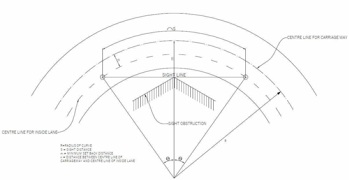
Due to the impracticality of maintaining visibility equivalent to the overtaking sight distance throughout the entire hill road, the alignment is strategically designed to ensure a minimum safe stopping sight distance. Consequently, the Indian Road Congress has stipulated specific minimum set-back distances on the inner side of horizontal curves, tailored to different speeds and radii of curves.

The setback distance is calculated from the equation:
\( m=R-\left(R-N\right)\cos\left(\theta\right) \)
where,
θ = S / (2 (R-n) ) radians
m = the minimum setback distance from the centre line of the road to sight obstruction in metres at the middle of the curve.
R= radius of the centre-line of the road in metres
n = distance between the centre line of the road and the inside lane in metres
S = sight distance in metres.
Transition Curves
A transition curve in road design is a gradual and smooth curve introduced between a straight path and a circular curve. Its purpose is to facilitate a seamless and gradual transition for vehicles moving from a straight alignment to a curved one or vice versa, minimizing abrupt changes in direction. This design element is crucial for ensuring driver comfort, reducing the effects of centrifugal force, and enhancing overall safety. Transition curves are carefully calculated to provide a gradual shift in curvature, allowing drivers to navigate the road more comfortably and predictably, particularly at higher speeds or on highways.
The minimum length of transition curves is to be calculated from the following two considerations and the larger of the two values adopted for design.
- The rate of change of centrifugal acceleration should not cause discomfort to drivers. From this consideration, the length of the transition curve is given by:

Here

(maximum values of 0.76 for speed less than 30 km/h)
Ls = Length of transition, metre
R = radius, meter
V = design speed, km/h
- The rate of change of superelevation should be such as not to cause discomfort to travellers or to make the road appear unsightly. The formula for the minimum length of transition on this basis is:
For Plain and Rolling Terrain:
Ls = 2.7V2/R
For Mountainous and Steep Terrain:
Ls = 1.0V2/R
The Indian Road Congress (I.R.C.) recommends minimum transition lengths for road design based on different speed categories. For design speeds up to 40 km/h, a minimum transition length of 10 meters is advised, while for design speeds ranging from 40 to 50 km/h, a longer transition of 20 meters is recommended.
Gradients on Horizontal Curves for Hill Road
The ruling and eliminating gradients in mountainous terrain and in steep terrain over 3000 m height above mean sea level are 5 and 6 per cent respectively. The ruling and limiting gradients in steep terrain up to 3000 m height above MSL are 6 and 7 per cent. At altitude greater than 3000m as the pulling power of engines decreases due to a reduction in oxygen supply, the design values of steepest gradients should be lower. Exception gradients steeper than the limiting gradient may be sparingly used, separated by a minimum length of 100 m.
At horizontal curves, the percentage compensation in gradient may be provided using the formula (30 + R)/R. The compensation gradients may not be however flatter than 4%.
Verticle Curves on Hill Road
The introduction of vertical curves at the intersections of varying grades on highways of mountainous and hilly terrain is imperative due to alterations in the vertical alignment. This measure is essential to create a smoother vertical profile, thereby mitigating sudden changes in gradients for swiftly moving vehicles.
Summit Curves
Summit curves occur at the crest of a hill, where the road changes direction from ascending to descending. These curves must be carefully designed to ensure smooth transitions and optimal visibility for drivers.
The length of the summit curve may be calculated by adopting a parabolic curve with the equation:
y = aX2
a = N/2L
Where,
N is a deviation angle
L= is the length of the curve
Valley Curves
Valley curves, also known as sag curves are situated at the bottom of a slope, marking the shift from a downward descent to an upward incline. There is no problem of restriction to sign distance in the valley curve during daylight.
The length of the valley curve for comfort condition is given by the equation
L = 2[Nv3/C]1/2
L= 0.38 (NV3)1/2
The length of the valley curve for headlight sight distance is given by the equation
L>SSD
L = NS/(1.5 +0.035S)
L<SSD
L = 2S – (1.5 +0.035S)/N
Here,
L = total length of valley curve, m
S = sight Distance (SSD), m
N = deviation angle = (n1 + n2), with slopes -n1 and +n2
Hairpin Bends
Hairpin bends on hill roads are unavoidable due to precipitous rock, deep valleys, and steep ascends leading to obligatory points. Within the limits of the available turning angle, laying cut curves following normal geometric standards of design is often very difficult and sometimes even impossible. A hairpin bend is strategically located on the hillside with the minimum slope and maximum stability. It must also be safe from the viewpoint of landslides and groundwater.
The following design criteria are adopted for planning hairpin bend:
- Minimum design speed = 20 km/h.
- The minimum radius of the inner curve = 14 m.
- Minimum length of transition = 15 m.
- Superelevation is a circular portion of the curve = 1 in 10
- The maximum and minimum gradients are 1 in 40 and 1 in 200 respectively at the curve.
- The minimum width of the carriageway at the apex of the curve is 11.5 and 9.0m for two-lane and single-lane pavements of the National and State Highways. The minimum width for MDR and ODR is 7.5 m.
- The approach gradient should not be steeper than 5 per cent for 40 m.
- The traffic island portion of the hairpin bend should be cleared of trees, etc. for good visibility.
Also, read: Traffic Islands: Types And Functionality
Cut Slops
The following side slopes are recommended at cut depending upon the soil types
| Type of Soil | Side slopes (vertical to horizontal) |
|---|---|
| Ordinary soils including moorum and hard clay | 1: 1 to 1: 1 1/2 |
| Disintegrated rock or conglomerate | 1: 1/2 to 1: 1/4 |
| Soft rock and shale | 1: 1 to 1: 1/8 |
| Medium rock | 1: 1 to 1: 1/16 |
| Hard rock | Nearly vertical ( or half-tunneling if the height of cut exceeds 7.5 m) |
Also, read: Embankment Construction: Materials And Specification
FAQs:
Q: What are Blind curves?
Ans: Blind curves refer to road segments where the available sight distance is shorter than the safe stopping distance, representing the absolute minimum from a safety standpoint. In these curves, there exists a constant risk of a vehicle being unable to halt before reaching a hazardous point or facing a potential collision with an oncoming vehicle due to insufficient sight distance.
Q: What are vertical curves?
Ans: Vertical curves are implemented to facilitate smooth transitions at changes in road grade. Convex vertical curves are commonly referred to as summit curves, while concave vertical curves are known as valley or sag curves. Both types of curves should be designed as square parabolas for optimal performance and geometric consistency.
The length of the vertical curve is controlled by the sight distance requirement. However, curves with greater length are aesthetically appealing.
References:
- Bhirud, L.L., Geometric Design of Hill Road, Journal, Indian Road Congress, Vol. XXXI-2 & 4.
- Indian Road Congress. (2019). Recommendations about the Alignment, Survey and Geometric Design of Hill Roads (Third Revision) (IRC: 52-2019). Kama Koti Marg, Sector-6, R.K. Puram, New Delhi-110022, India.
- Indian Roads Congress. (1998). Hill Road Manual (Reprinted 2015) (IRC: SP: 48-1998). Jamnagar House, Shahjahan Road, New Delhi-110011, India.
- Khanna, S.K., & Justo, C.E.G. (1971). Highway Engineering (8th ed). Roorkee (U.A.): Nem Chand & Bros. https://www.google.bt/books/edition/Highway_Engineering/CYOeQwAACAAJ?hl=en
![]()


