Joints in Concrete Pavements:
Joints in concrete pavements are provided in a pavement slab in order to allow for movement caused by changes in moisture content and slab temperature. Transverse joints across the pavement at right angles to its centreline permit the release of shrinkage and temperature stresses. The greatest effect of these stresses is in the longitudinal direction. Longitudinal joints, on the other hand, deal with induced stresses most evident across the width of the pavement.
The weight of the pavement slab prevents it from warping, which would cause stress known as wrapping stress. Warping stresses are highest in the interior region and lowest at the corners. During daytime warping downward, the bottom of the slab experiences tensile stresses. Conversely, when the slab warps upward, tensile stresses occur at the top. To reduce temperature-induced stresses, transverse expansion, contraction, and warping joints can be incorporated across the entire width of the pavement.
Types of Transverse Joints
There are four main types of transverse joints:
- Contraction joints
- Expansion joints
- Warping joints
- Construction joints.
Contraction Joints
Contraction occurs when water is lost or temperatures drop. Expansion occurs when water is absorbed or the temperature rises. The insertion of contraction and expansion joints permits movement to happen.
The contraction joints are constructed in the transverse direction to relieve tensile stresses that develop because of thermal contraction and force the slab to crack at a pre-determined position.
Contraction joints are strategically placed to allow for the natural contraction of the slab. These joints are spaced closer together compared to expansion joints. The transfer of loads at these contraction joints occurs through the physical interlocking of the aggregate protruding from the joint faces. According to IRC specifications, the maximum spacing for contraction joints in unreinforced cement concrete slabs is 4.5 meters, while for reinforced slabs with a thickness of 20 centimetres, it is 14 meters.
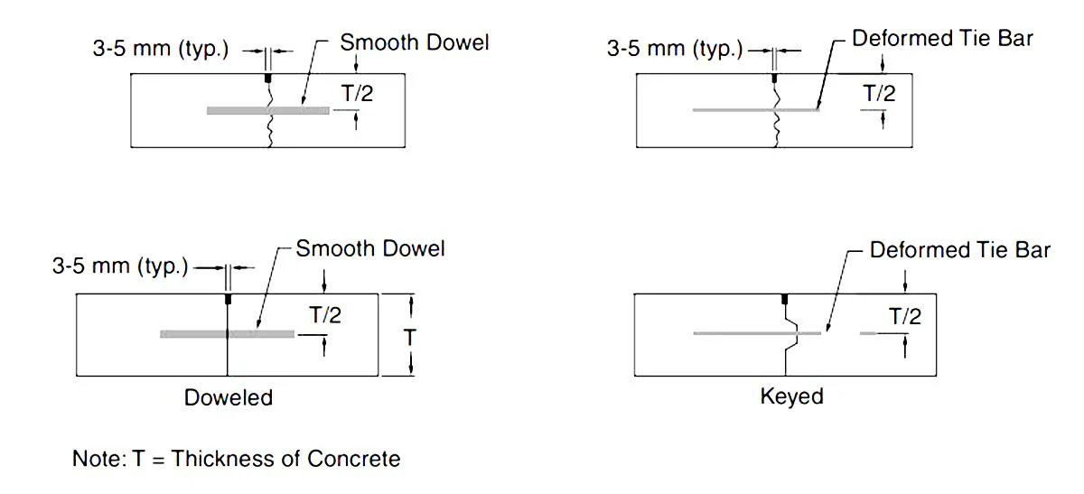
Given the recommended close spacing of contraction joints, the primary mechanism for load transfer is indeed the interlocking of aggregates within the concrete. However, to enhance safety and ensure reliable load transfer, certain agencies recommend the use of fully bonded dowel bars embedded within the concrete. These dowel bars serve as an additional measure to secure load transfer at contraction joints.
Contraction joints allow induced stresses to be released by permitting the adjacent slab to contract, thereby causing a reduction in tensile stresses within the slab. The joint, therefore, must open to permit this movement while at the same time prohibiting vertical movement between adjacent concrete slabs. Furthermore, water should not be allowed to penetrate the foundation of the pavement. The joint reduces the thickness of the concrete slab, inducing a concentration of stress and subsequent cracking at the chosen appropriate location. The reduction in thickness is usually achieved by cutting a groove in the surface of the slab, causing a reduction in depth of approximately 30%. A dowel bar placed in the middle of the joint delivers the requisite vertical shear strength across it and provides load-transfer capabilities. It also keeps adjacent concrete surfaces level during temperature-induced movements. To ensure full longitudinal movement, the bar is debonded on one side of the contraction joint.
Expansion Joints
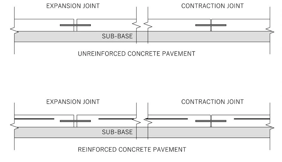
These joints are provided to allow for the expansion of the slabs due to a rise in slab temperature above the construction temperature of the cement concrete. Expansion joints also permit the contraction of slabs. Expansion joints are provided at an interval of 50 to 60 metres for a smooth interface laid in winter and 90 to 120 meters for a smooth interface laid in summer. However, for the rough interface, the spacing between expansion joints maybe 140 metres. The approximate gap width for this type of joint is from 20 to 25 mm.
It may be stated here that the break in slab continuity forming a joint adds a weaker plane in the cement concrete pavement. The stresses include due to the wheel loads at such joints being very high order at the edge and corner regions. To strengthen these locations, the following are adopted.
The load transfer across the transverse joint is carried out through a system of reinforcement provided at suitable intervals projecting in the concrete in the longitudinal direction up to 60 cm in length. Such a device is named a dowel bar. In the expansion joint, load transference is affected through a system of dowel bars, Dowel bars are embedded and kept fixed in concrete at one end and the other end is kept free to expand or contract by providing a thin coating of bitumen over it. The metal cap is provided at this end to offer a space of about 2.5 cm for movements during expansion. In this design, 40 per cent of the wheel load is expected to be taken up by the group of dowel bars and transferred to the adjoining slab.
The width of the expansion joint is calculated from the equation
Also, read: Dowel Bars: A Key Element For Durability And Load Transfer
Warping Joints
Warping joints are required in plain unreinforced concrete slabs only. They permit small angular movements to occur between adjacent concrete slabs. Warping stresses are very likely to occur in long narrow slabs. They are required
in unreinforced slabs, only, as in reinforced slabs the warping is kept in check by the reinforcing bars. They are simply a sealed break or discontinuity in the concrete slab itself, with tie bars that restrict any widening and hold the sides
together.
This type of joint is often referred to as a “hinged joint.” Longitudinal joints that incorporate tie bars belong to this category of joints. These joints are seldom required if well-designed expansion and contraction joints are implemented effectively to prevent the occurrence of cracking.
Construction Joints
Construction joints are incorporated to connect concrete segments that have been laid at different times. These joints are usually established with the assistance of a bulkhead, and it is crucial to exercise caution to guarantee that the concrete adjacent to the bulkhead is sufficiently vibrated to avoid the formation of voids or imperfections.
Isolation joints, on the other hand, serve to create a separation between the pavement and nearby objects or structures. They enable the pavement section to move independently of the adjacent object, preventing any potential damage.
At both isolation joints and construction joints, bond breakers are commonly employed. These bond breakers can be as simple as lubricants or materials such as pressboard, which ensure that there is no adhesive bond between the concrete sections.
Longitudinal Joints
Longitudinal joints may also be required to counteract the effects of warping along the length of the slab. They are broadly similar in layout to transverse warping joints.
Arrangement of Joints
The joints in the transverse direction are placed as follows:
- Staggered arrangement
- Uniform arrangement
- Sket arrangement
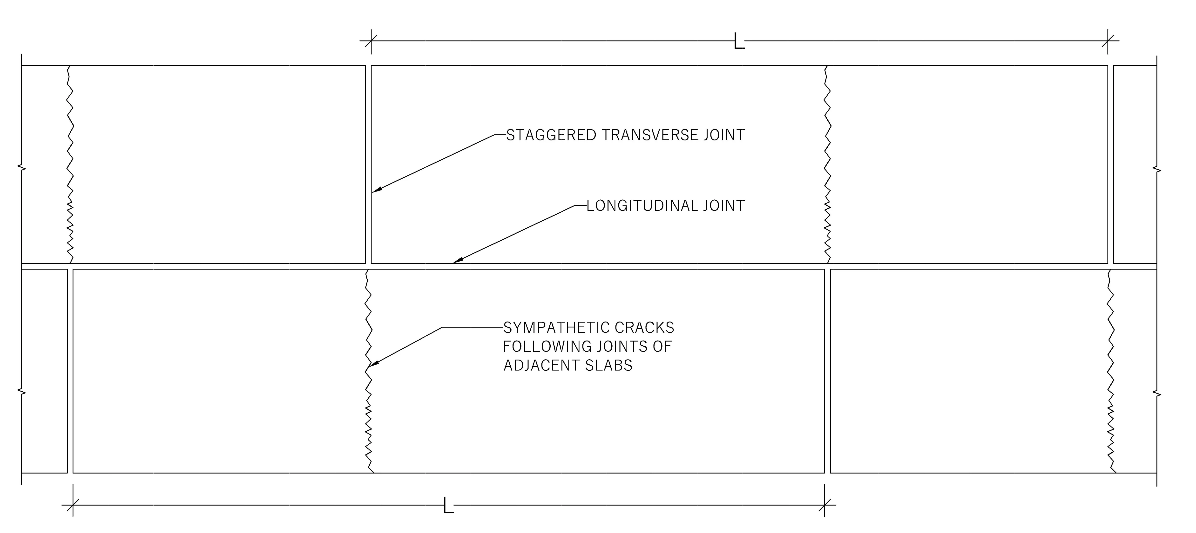
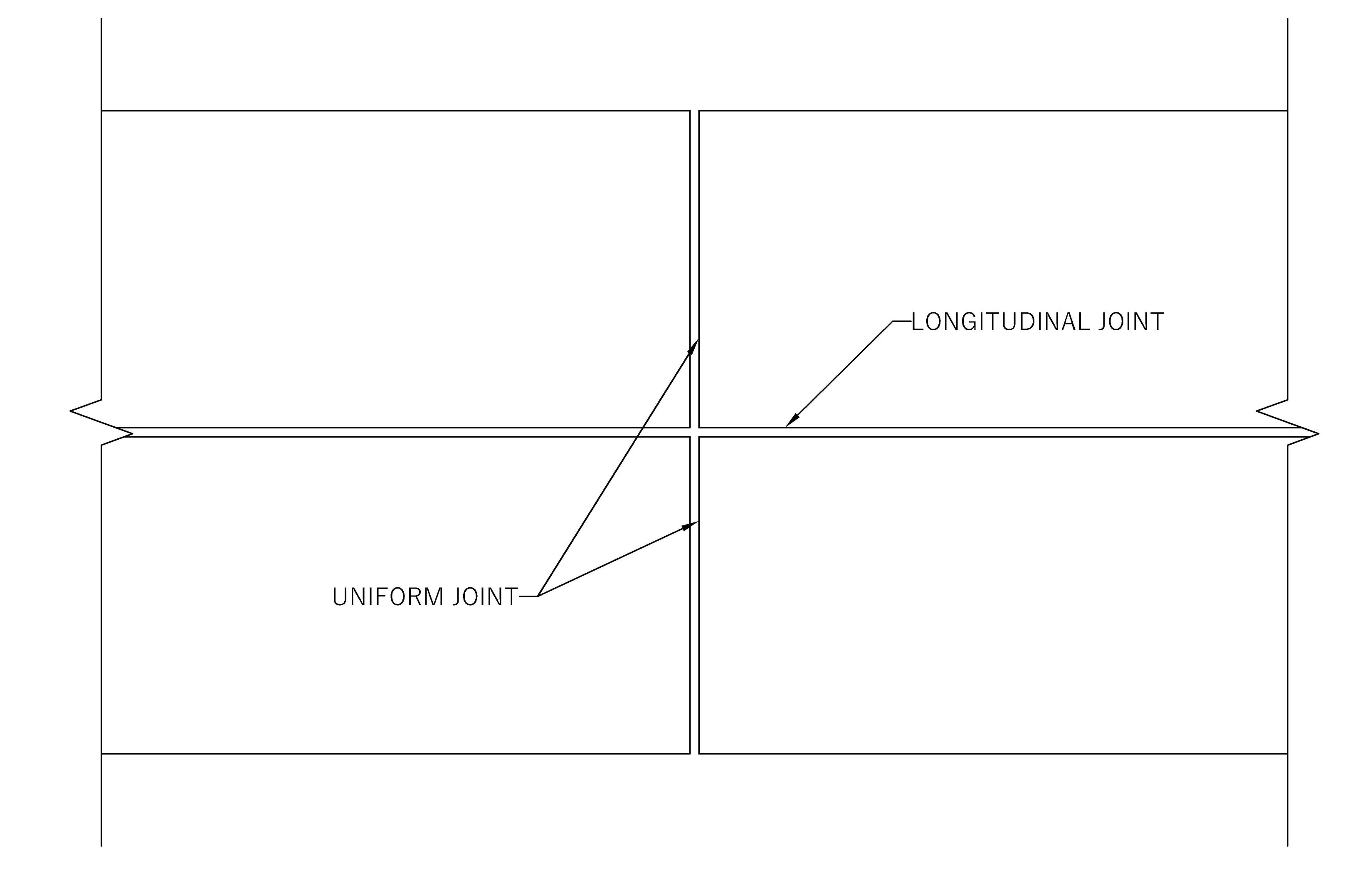
Observations indicate that when transverse joints are positioned in a staggered manner on both sides of the longitudinal joints, as depicted in Figure A, sympathetic cracks often appear parallel to the transverse joints. To prevent this, it is advisable to install joints that align across the longitudinal joints in the same transverse pattern, as demonstrated in Figure B.
While it is generally preferred to avoid skewed joint alignments, there are instances, especially at intersections in specific layouts, where a skewed arrangement may be necessary. In cases where a skewed arrangement cannot be avoided, reinforcement is used to enhance the strength of the acute corners, as illustrated in Figure C.
FAQs:
Q: What should be the spacing of contraction joints in cement concrete pavement?
Ans: According to IRC specification, for unreinforced cement concrete pavement, the spacing between contraction joints should be 4.5 meters and for reinforced cement concrete pavement it should be 14 meters for a 20 cm thick slab.
Q: How do you calculate expansion joints in concrete pavements?
Ans: As per Indian Standard 456: 2000, cl.27.2 structures with a length of 45 meters are designed with one or more expansion joints. However, there are many factors to designing the expansion joint and IS 3414 gives the design consideration. Joints in concrete pavements or concrete slabs may be calculated from the equation:
w= L.T.C
where,
w is the width of the expansion joint
L is the length of the concrete member
T is the temperature difference
C is the coefficient of thermal expansion of concrete (thermal expansion of concrete is 12/1000000 per degree centigrade.
Q: Why warping joints are provided?
Ans: Warping joints are provided to the unreinforced cement concrete pavement to prevent stresses due to the warping of the slab. Warping stresses are very likely to occur in long narrow unreinforced cement concrete slabs.
References:
- Khanna, S.K. & Justo C.E.G. (2001). Highway Engineering (8th ed.) Nem Chand & Bros., Civil Lines, Roorkee.
- Rogers, M. (2003). Highway Engineering. Blackwell Publishing.
- Nikolaides, A. (2015).Pavements, Materials and Control of Quality. Highway Engineering. Taylor & Francis Group. Boca Raton. London. New York
- Indian Standards Institution. (1968). IS: 3414-1968: Code of practice for design and installation of joints in buildings. Bureau of Indian Standard
- Indian Standard Institution. (2000). IS: 415-2000. Plain and reinforced concrete – Code of practice (4th rev.). Bureau of Indian Standard
![]()


