The scale in engineering drawings represents the size of objects in a reduced or enlarged format. They help in conveying the dimensions and proportions of the objects accurately.
The proportion by which we either reduce or increase the actual size of the object on a drawing is known as scale.
Sizes of Scale in Engineering Drawing
The size of scale in engineering drawings can vary depending on the size of the object that is to be represented in the drawing sheet. A smaller object may need to be drawn on the enlarged scale or the object may need to be reduced in size in the drawing as per the need or to fit in the paper. Therefore, three sizes of scale are identified as stated below.
Full-size scale:
The scale in which the actual measurements of the object are drawn to the same size on the drawing is called a full-size scale. 1:1= drawing made to actual size.
Reducing scale:
The scale in which the actual measurement of the object is reduced to some proportion is known as reducing scale. The standard reducing proportions are:
- 1:2= drawing made to one-half of the actual size
- 1:5 = drawing made to one-fifth of the actual size
- 1:10 = drawing made to one-tenth of the actual size
- 1:20 = drawing made to one-twentieth of the actual size
- 1:50 = drawing made to one-fiftieth of the actual size
- 1:100 = drawing made to one-hundredth of the actual size
Enlarging scale
The scale in which the actual measurement of the object is increased to some proportion is known as the enlarging scale. The standard proportions are:
- 2:1 = drawing made to twice the actual size
- 5:1 = drawing made to five times the actual size
- 10:1 = drawing made to ten times the actual size
Representative Fraction (RF):
The ratio of the distance on the drawing sheet of an object to the corresponding actual distance of the object (measured in the same unit) is known as the representative fraction (R.F) or scale factor. It is a common way to express the scale of a drawing. For example, if the RF is 1:50, it means that one unit on the drawing represents 50 units in the actual object.

For example,
If a 5 m distance is represented on a drawing by a line 50 mm, then the RF of the scale on which the drawing is made will be 50 mm ÷ 5000 mm = 1 ÷ 100 (for a reduced scale)
Therefore, RF = 1:100.
If a 5 mm distance is represented on a drawing by a line of 50 mm, then the RF of the scale will be 50 mm ÷ 5 mm = 10 ÷ 1 (for an enlarged scale)
Therefore, RF = 10:1.
Types of Scales
The types of scales used in engineering practice are classified as under:
- Plain scales
- Diagonal scales
- Comparative scales
- Vernier scales
- Scale of chord
Plain Scale (or Linear Scale)
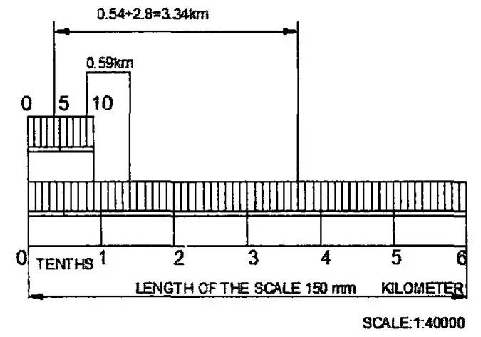
A plain scale is a linear representation tool that consists of a line divided into a suitable number of equal parts or units, where the first unit is subdivided into smaller parts. This series of lines or marks on the scale corresponds to specific units of length. In engineering drawings, the actual lengths of objects are directly measured using a plain scale, with each marked unit representing a designated value on the drawing scale. This straightforward approach allows for the accurate portrayal and measurement of lengths within the context of the chosen drawing scale.
The scale is usually placed along one of the edges of the drawing, and measurements are taken directly from it. Common units on a plain scale include millimetres, centimetres, inches, etc.
Feature of Plain Scale:
- In every scale, the zero should be placed at the end of the first main division, i.e. between the unit and its subdivisions.
- From the zero mark, the units should be numbered to the right and their sub-divisions to the left.
- The names of the units and the sub-division should be stated clearly below or at the respective ends.
- The name of the scale (for example, a scale of 1:10) or its RF should be mentioned below the scale.
Also, read: How To Prepare Structural Drawings?
Diagonal Scale
A diagonal scale is used when a higher degree of accuracy is required than what can be achieved with a plain scale. It consists of a series of diagonal lines intersecting with horizontal and vertical lines. Each diagonal line represents a certain scale, and measurements can be taken by following the diagonal lines.
Principle of Diagonal Scale:
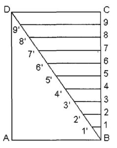
To obtain the division of a given short line AB in multiples of 1/10 its length, for example, 0.1 AB, 0.2 AB, 0.3 AB, etc. from figure (1).
- At one end, say C draw a line perpendicular to CD and along it, step off ten equal divisions of any length, starting from B and ending at B.
- Number the division points, 9, 8, 7, … 1 as shown.
- Joint D with B.
- Through the points, 1, 2 etc. draw lines parallel to CD and cut BD at 1′, 2′ etc. It is evident that triangles 1’1B, 2’2B … ABC are similar.
- Similarly, 1’1 = 0.1 CD, 2’2 = 0.2 CD, etc.
Thus, each horizontal line below CD becomes progressively shorter in length by 1/10 CD given length in multiples of 0.1 CD.
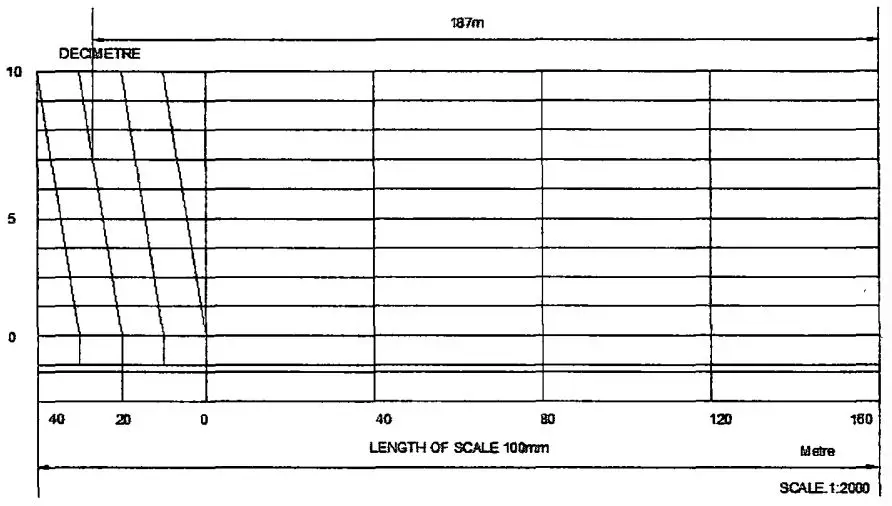
Comparative Scale
This type of scale has the same representative fraction but graduates to read different units are called comparative scale. A drawing drawn with a scale reading inch units can be read in metric units by means of a metric comparative scale, constructed with the same representative fraction. Comparative scales may be plain scales or diagonal scales and may be constructed separately or one above the other.
Vernier Scale
It is a type of diagonal scale that is used to read to a very small unit with greater accuracy. A vernier scale consists of two parts- a primary scale and a vernier. The primary scale is a plain scale fully divided into minor divisions.
As it would be difficult to subdivide the minor divisions in an ordinary way, it is done with the help of the vernier. The graduations on the vernier are derived from those on the primary scale.
- Principle of Vernier Scale:
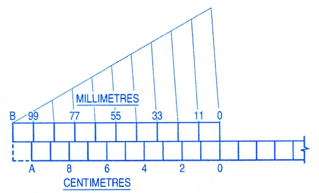
Figure (2) shows a part of a plain scale in which the length A0 represents 10 cm. If we divide A0 into ten equal parts, each part will represent 1 cm. It would not be easy to divide each of these parts into ten equal divisions to get measurements in millimetres.
Now, if we take a length B0 equal to 10 + 1 = 11 such equal parts, thus representing 11 cm, and divide it into ten equal divisions, each of these divisions will represent 11÷10 = 1.1 cm or 11 mm.
The difference between one part of A0 and one division of B0 will be equal to 1.1 – 1.0 = 0.1 cm or 1 mm.
Similarly, the difference between two parts of each will be 0.2 cm or 2 mm.
The upper scale B0 is the vernier. The combination of the plain scale and the vernier is the vernier scale.
In general, if a line representing n units is divided into n equal parts, each part will show n/n = 1 unit. But, if a line equal to n + 1 of these units is taken and then divided into n equal parts, each of these parts will be equal to (n + 1)/n = 1 + 1/n units.
The difference between one such part and one former part will be equal to (n + 1)/n – n/n = 1/n unit.
Similarly, the difference between the two parts will be 2/n unit.
- Least Count of Vernier Scale: It is the difference between 1 primary scale division and 1 vernier scale division. It is denoted by ∠C. ∠C = 1 primary scale division – 1 vernier scale division. The vernier scale division is as under:
- Forward vernier: In this case, the length of one division of the vernier scale is smaller than the length of one division of the primary scale. The vernier divisions are marked in the same direction as that of the main scale.
- Backward vernier: The length of each division of the vernier scale is greater than the length of each division of the primary scale. The numbering is done in the opposite direction as that of the primary scale.
Also, read: Structure Drawing Detailing For Reinforced Concrete Structures
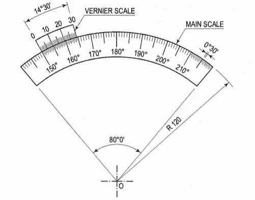
Circular Vernier
The circular vernier is used in surveying instruments to measure angle to the required accuracy. In the case of mechanical engineering, it is used in measuring instruments such as micrometres.
Scale of Chords
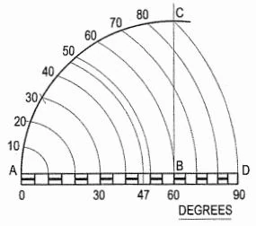
The scale of chords as shown in Figure (5), is used to set out or measure angles when a protractor is not available. It is based on the length of the chords of different angles measured on the same arc and is constructed as shown below.
- Draw a line AB of any length
- At B, erect a perpendicular
- With B, as a center, describe an arc AC cutting the perpendicular at a point C. Then, the arc AC (or the chord AC) subtends an angle of 90° at the centre B.
- Divide AC into nine equal parts. This may be done
- by dividing the arc AC into three equal parts by drawing arcs with centres A and C and radius AB, and then
- by dividing each of these parts into three equal parts by trial and error method. Each of the nine equal parts subtends an angle of 10° at the center B.
- Transfer each division point from the arc to the straight line AB produced, by taking A as centre and radii equal to chords A -10, A -20, etc.
- Complete the scale by drawing a rectangle below AD. The divisions obtained are equal, decreasing gradually from A to D. It is quite evident that the distance from A to a division point on the scale is equal to the length of the chord of the angle subtended by its at the centre B. It may be noted that the chord A -60 is equal to the radius AB.
FAQs:
Q: Which scale is used to represent three units?
Ans: Diagonal scales are used to represent either three units of measurement such as meters, decimetres, or centimetres or to read the accuracy correctly to two decimals.
Q: What is the least count of the vernier scale?
Ans: The least count (LC) is the smallest dimension correct to which a measurement can be made with a vernier scale.
For forward vernier, LC = 1 msd – 1 vsd
For backward vernier, LC = 1 vsd – 1 msd
Where “msd” is a main scale division and “vsd” is an vernier scale division.
References:
- Bhatt, N.D (2011). Engineering Drawing (Plane and Solid Geometry) (5th revision). Charotar Publishing House Pvt. Ltd. Anand 388 001 Gujarat. India
- Reddy, K. Venkata (2008). Textbook of Engineering Drawing (2nd edition). BS Publications. Giriraj Lane, Sultan Bazar, Hyderabad
![]()


