Tension members and compression members are two types of structural elements that are the backbone of the steel structure. They experience forces in tension or compression. These terms are commonly associated with materials like steel, which are used in the construction of various types of structures such as buildings, bridges, and towers.
What is Tension Member?
In structural engineering, tension members are structural elements that primarily carry axial loads in tension. These members are designed to resist forces that act to pull or stretch the material, causing it to elongate. Tension members are crucial components in various types of structures, providing stability and support.
Types of Tension Members
The various forms of tension members include:
- Cables, Ropes and Wires
- Bars and Rods
- Plates and Flat Bars
- Single Structural Shapes
- Built-Up Sections
Cables, Ropes and Wires
These are perhaps the most straightforward examples of tension among members. They are often used in suspension bridges, cable-stayed bridges, and other structures where the ability to carry tensile loads over long spans is essential.
The cables and ropes are fundamental tension members that play a crucial role in various applications. These elements are designed to carry loads primarily in tension, resisting forces that attempt to pull or stretch the material. Here’s an explanation of cables and ropes in the context of structural engineering:
Cables: Cables are generally larger-diameter, high-strength steel wires or strands twisted or braided together to form a flexible structure with high tensile strength. They are commonly used in structural systems where long spans and high strength are required, such as suspension bridges and cable-stayed bridges.
Bars and Rods
These are some of the simplest forms of tension members. Bars and rods are slender structural members used to stabilize and support structures. They are often used as tension members in bracing systems; as sag rods to support purlins between trusses, and to support girts in industrial buildings, where a light structure is desirable for example tower masts etc.
Rods play a role in arches by providing resistance against the arch’s thrust. However, they are currently not preferred by designers due to the significant lateral displacement they cause in strong winds and the disruptive noise caused by vibrations. The utilization of rectangular bars is decreasing, although they may still be employed as hangers in specific structures. Eye bar tension members find application in truss bridges, suspension bridge chains, and as hangers for floor beams in both suspension and arch bridges.
Plates and Flat Bars
Plates and flat bars frequently serve as tension members in structures such as transmission towers and footbridges. Additionally, they play a crucial role in columns, ensuring the proper positioning of component members. Examples include lacing flats, batten plates, end tie plates, and similar elements.
Single Structural Shapes
A single plate, oriented vertically or horizontally, can act as a tension member. The specifications outline the design considerations for single plates subjected to tensile forces.
Built-Up Sections
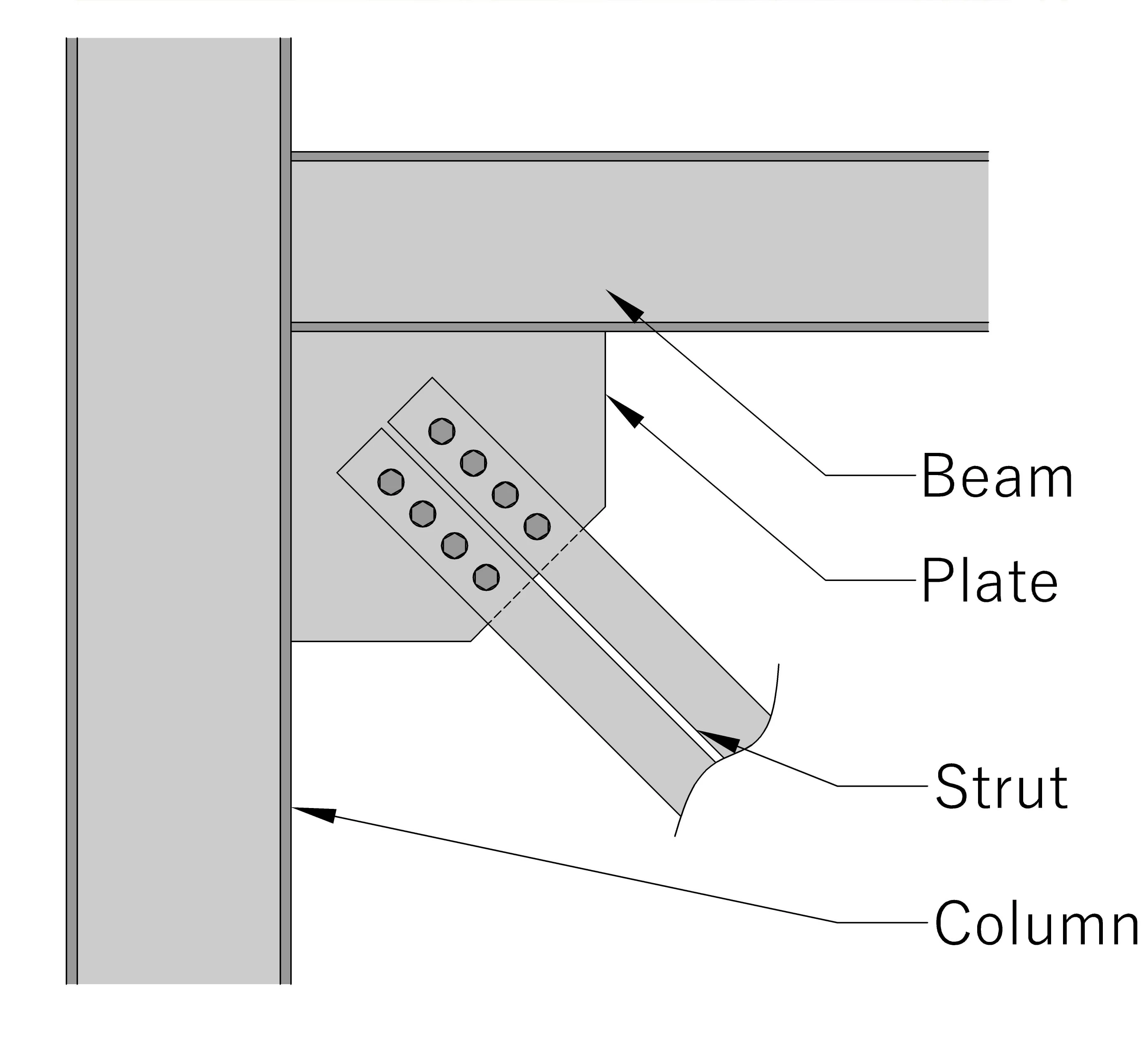
Generally, the term “built-up section” in steel structure refers to the element that is composed of two or more smaller and standard steel sections, such as plates, angles, channels, I beam or other standard sections, assembled and welded or riveted or bolted together to act as single and more complex structural member. The purpose of creating a built-up section is to achieve specific design objectives or to meet the required area that may not be easily attainable with single-rolled sections.
Built-up members are tougher because, for the same size, they can resist bending better by having a much larger moment of inertia compared to single-rolled sections. Another benefit is that built-up members can be made strong enough to handle both compression and tension, making them useful when stresses change direction.
The built-up section may be subjected to tension and other load simultaneously. For example, the gusset plate is equipped with angle portions affixed to each of its sides. When the angle sections are positioned on the same side of the plate, the gusset plate can withstand both tension and bending forces.
Also, read: What Is Structural Steels? | Types | Usage
Net Section Area (An)
The net sectional area of a tension member is the total sectional area of the member minus the sectional area of the maximum number of holes. It is important to consider the net section when calculating stresses because sections with holes are prone to failure. Even if a hole is filled with a bolt, the unit stress in a tension member increases. This is because the steel area carrying the load is reduced, leading to some stress concentration along the hole edges.
An = Ag – Sectional areas of holes
Where,
An = net sectional area of plate
Ag = gross sectional area of plate
Net Section Area (Ane)
The modified net area is called effective net area and may be defined by the following equation
Ane = K1K2K3K4An
Ductility Factor (k1)
The net section strength of a tension member increases with the ductility of steel. For common structural steels exhibiting minimum specified ductility, the value of k1 is 1.0
Factor for Method of Fabrication (k2)
In bolted connections, holes are created through either punching or drilling, with the latter being a superior but more expensive method. When holes are punched, the material around them undergoes shear deformation beyond its ultimate strength. As a result, the strength of the member may be reduced by approximately 10 to 15 per cent compared to holes drilled. This reduction is attributed to the strain hardening of the material surrounding the punched hole, leading to a loss of ductility. Certain specifications designate a factor of 0.85 for punched holes and 1.0 for drilled holes to account for this difference.
IS: 800–2007 specifies an increased hole diameter by 2 mm while calculating net areas of
punched holes instead of using k2 = 0.85.
Geometry Factor (k3)
The efficiency of bolted joints (for the net sections) is inversely proportional to the gauge/diameter (g/d) ratio.
The value of k3 varies between 0.9 and 1.14. However, IS: 800–2007 specifies it to be unity.
Ductility Factor (k4)
The efficiency of a tension member relies on its connection method. For members that aren’t flat or bar-shaped, the actual tensile stress is likely to be lower than the steel’s coupon tensile strength until a fracture happens across its critical section. This is true unless all the components forming the section are interconnected in a way that ensures uniform stress transfer across the entire section.
Slenderness Ratio of Tension Members
In tension members, the slenderness ratio is determined by the ratio of their unsupported length to their smallest radius of gyration. Nevertheless, as per IS: 800 (2007) standards, the maximum effective slenderness ratio is defined as the ratio of the effective length of the member to the least radius of gyration. Even though tension members don’t typically experience buckling, IS 800 introduces a restriction on the maximum slenderness ratio. This precautionary limit is established to mitigate the potential risk of buckling that might arise during load reversals, serving as a preventive measure outlined in the code.
Behaviour of Tension members
As tension members experiencing axial loads undergo uniform tensile stress, their response to deformation closely resembles the fundamental stress-strain characteristics of the underlying material. For mild steel members, such as those conforming to IS: 2062 & IS: 226 standards, the load-deformation pattern includes an elastic phase (a-b) concluding at the point of yielding (b). Subsequently, a yield plateau (b-c) ensues, during which the load remains consistent while elongation expands to approximately ten times the yield strain.
Upon additional stretching, the material demonstrates a lesser rise in tension with elongation (c-d) in comparison to the initial elastic range. This phase is commonly known as the strain-hardening range. Following the attainment of the ultimate load (d), the applied load decreases while elongation continues to increase (d-e) until eventual rupture (e). In tension members made of high-strength steel, a distinct yield point and yield plateau are typically absent (Fig. 4.3). In such instances, the 0.2% offset load, denoted as T in Fig. 4.3, is commonly considered as the yield point.
Also, read: Types Of Steels And Their Usage In Construction
Design Strength Due to Yielding of Gross Section
Although steel tension members can sustain loads up to the ultimate load without failure, the elongation of the members at this load would be nearly 10 to 15% of the original length and the structure supported by the member would become unserviceable. Hence, in the design of tension members, the yield load is usually taken as the limiting load. The corresponding design strength in the member under axial tension is given by
Td = fy.A/γmo …1
where,
fy = the yield strength of the material
A = is the gross area of cross section in mm2
γmo = the partial safety factor for failure in tension by yielding. Its value according to IS800 is 1.10.
Design Strength Due to Rupture of Critical Section
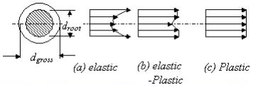
Plates subjected to tension often incorporate bolt holes. Within the elastic range of Tension Member behaviour, the tensile stress in a plate at the cross-section of a hole is not evenly distributed but displays stress concentration near the hole, as illustrated in Figure 2. The Stress Concentration Factor is defined as the ratio of the maximum elastic stress near the hole to the average stress on the net cross-section. This factor typically falls within the range of 2 to 3, depending on the ratio of the hole diameter to the width of the plate perpendicular to the direction of stress.

In tension members subject to static loading and featuring a hole, the area adjacent to the hole attains the yield stress, fy, initially. As loading continues, the stress at this location remains constant at the yield stress, and plastic deformation progressively extends away from the hole [see Fig. 2 (b)]. This process persists until the entire net section around the hole reaches the yield stress, fy [see Fig. 2 (c)]. Ultimately, the member experiences rupture (tension failure) when the entire net cross-section reaches the ultimate stress, fu [see Fig. 2 (d)].
As only a limited length of the member near the smallest cross-section at the holes undergoes significant elongation at the ultimate stress, the overall member elongation doesn’t necessarily have to be substantial, provided that the stresses in the gross section remain below the yield stress. Therefore, the design strength, as dictated by the net cross-section at the hole, Tdn, is expressed by equation (C1.6.3).
Ptn = 0.9fu.An / γm1 …2
Where,
fu = the ultimate stress of the material,
An = the net area of the cross-section after deductions for the hole [Fig.2 (b)]
γm1 is the partial safety factor against ultimate tension failure by rupture ( γm1 is 1.25 according to IS800).
Likewise, when threaded rods are under tension, failure may occur due to rupture at the root of the threaded region. Therefore, the net area, An, corresponds to the root area of the threaded section, as illustrated in Figure 3.
The lower value of the design tension capacities, as given by equations 1 and 2, governs the design strength of a plate with holes.
Frequently, plates have more than one hole for making connections. These holes are usually made in a staggered arrangement [Fig.4 (a)].
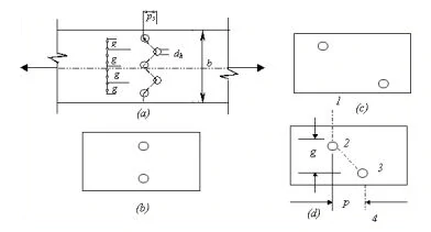
Let’s examine two contrasting configurations of two bolt holes in a plate, as depicted in Figures 4 (b) and 4 (c). In the scenario illustrated in Figure 4 (b), the gross area undergoes a reduction by two bolt holes to derive the net area. Conversely, in the arrangement depicted in Figure 4 (c), only one hole deduction is required when determining the net area of the cross-section. The transition in net area from the scenario presented in Figure 4 (c) to Figure 4 (b) must be gradual.
When the pitch length (the centre-to-centre distance between holes along the stress direction), denoted as p, is reduced, the critical cross-section undergoes a transition from a straight section [see Fig. 4 c)] to a staggered section 1-2-3-4 [see Fig. 4 (d)]. At this point, the net area experiences a reduction due to the presence of two bolt holes along the staggered section, but it concurrently increases due to the inclined leg (2-3) of the staggered section.
The net effective area of the staggered section 1-2-3-4 is given by
An = (b – 2d + p2 / 4g ) t …3
Where,
An = the net area of the cross-section after deductions for the hole [Fig.4 (b)]
b = the width of the plate in mm
d = diameter of the hole in mm
p = pitch distance in mm
g = the gauge distance in mm
In equation 3, the increase of net effective area due to the inclined section is empirical and is based on test results. It can be seen from Eqn.4.3 that as the pitch distance, p, increases and the gauge distance, g, decreases, the net effective area corresponding to the staggered section increases and becomes greater than the net area corresponding to a single bolt hole. This occurs when
p2 = 4g > d …4
When multiple holes are arranged in a staggered fashion in a plate as shown in Fig.4 (a), the net area corresponding to the staggered section in general is given by
Anet = [ b – nd + Σp2 / 4g ] t …5
Where,
n = the number of bolt holes in the staggered section.
Design Strength Due To Block Shear
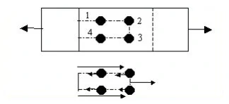
A tension member may fail along the end connection due to block shear as shown in Figure 5. The corresponding design strength can be evaluated using the following equation. The block shear strength at the end connections is taken as the smaller of (C1.64)
Tdb = [ Avg.fy / ( √ 3 γmo ) + fu.Atn / γm1 ] …6
Or
Tdb = [ Avg.fy / ( √ 3 γm1 ) + fy.Atg / γmo ] …7
Where,
Avg, Avn = minimum gross and net area in shear along a line of transmitted force, respectively.
Atg, Atn = minimum gross and net area in tension from the hole to the toe of the angle or next last row of the bolt in plates, perpendicular to the line of force, respectively.
fu, fy = ultimate and yield stress of the material respectively
FAQs:
Q: What are common examples of tension members?
Ans: The common examples include cables, ropes, rods, and other elements that are designed to resist pulling forces.
Q: How are tension members different from compression members?
Ans: Tension members experience forces that tend to elongate or pull them apart, while compression members experience forces that tend to shorten or compress them.
Q: How is the strength of a tension member determined?
Ans: The strength is often governed by the yield strength of the material used as yield load is taken as the limiting load
Q: What is the significance of the effective net area in tension members?
Ans: The effective net area is a reduced area used in calculations to account for holes, openings, or other irregularities in the cross-sectional area of the tension member.
Q: How are connections designed for tension members?
Ans: Connections must be designed to transfer the applied tensile force efficiently. Common types include bolted connections and welded connections.
References:
- IS 800-2007. Code of practice for general construction in steel, Bureau of Indian Standards, New Delhi.
- Duggal,.S.K. (2014). Limit State Design of Steel Structures (2nd Edition).
- McGraw Hill Education (India) Private Limited
- Dowling P.J., Knowles P. and Owens GW., Structural Steel Design, The Steel Construction Institute, 1988.
- Owens GW and Knowles PR, Steel Designers Manual’, fifth edition, Blackwell Science 1992
- Wikipedia contributors. (2019, August 4). Tension member. Wikipedia. https://en.wikipedia.org/wiki/Tension_member
- Mishra, G. (2016, September 20). Types of tension members in structural steel construction. The Constructor. https://theconstructor.org/structural-engg/types-of-tension-members/4800/
![]()

