Tie bars, which may take the form of deformed steel bars or epoxy-coated steel connectors, maintain contact between the faces of rigid slabs, as outlined by AASHTO in 1993. Typically positioned across longitudinal joints or between an edge joint and a curb or shoulder, their primary objectives are to prevent lane separation, minimize differential deflection, and reduce transverse cracks by ensuring that adjacent slabs remain in contact. It’s essential to understand that while tie bars provide some level of load transfer, they are not intended for this function and should not be used as load transfer devices.
These bars are specifically employed at the longitudinal joints of cement concrete pavements to securely unite two adjacent slabs. Designed to withstand tensile stresses, they are engineered to counteract the force required to overcome the frictional resistance between the bottom of the adjoining pavement slab and the soil subgrade, particularly at the joint location leading to the subsequent joint or free edge.

The area of steel per meter length of the joint is obtained by equating the total subgrade friction to the total tension developed in the Tie bars.
Also, read: What Is Rigid Pavement? | 4 Types Of Rigid Pavement
Diameter and Spacing
The diameter and spacing of the tie bars are calculated as explained under:
Thus considering the one-meter length of the joint
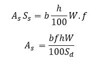
Where
As = area of steel per meter length of the joint, cm3
b = distance between the joint and nearest free edge, m
h = thickness of pavement, cm
f = Coefficient of friction between pavement and subgrade (may be taken as 1.5 for rough interface)
W = unit weight of cement concrete, kg/m3 (2400 kg/m3) Ss = allowable working stress in tension for steel, kg/m2 (1400kg/m2)
Assuming a suitable diameter of the tie bar (0.8 to 1.5 cm) the spacing of the tie bar can be found to provide the area of steel As cm2 per meter length of the slab.
Length of Tie Bar
The total length of the Tie bar should be at least twice the length of embedment required on each slab to develop a bond strength equal to the working stress of the steel.
This is obtained from the consideration that the total tensile force developed in the Tie bar should not exceed the bond strength between the Tie bar and the concrete. Therefore, considering one side of the longitudinal joints.
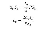
Substituting as = πd2/4 and P=πd
The total length of the Tie bar is

Here,
Lt = length of Tie bar on one side of slab, cm or half length of Tie bar
SS = allowable stress in tension, kg/cm2 (1400 kg/cm2)
Sb = allowable bond stress in concrete, kg/cm2 (this is taken as 24.6 kg/cm2 for deformed bars and 17.5 kg/cm2 in plain Tie bar)
as = cross-sectional area of one Tie bar, cm2
P = perimeter of Tie bar, cm
d = diameter of tie bar, cm
Also, read: Joints In Concrete Pavements: Transverse Joints & Longitudinal Joints
Position of Tie Bars
Tie bars must be accurately placed within the upper middle third of the slab depth, as depicted in the drawings, maintaining an approximately parallel orientation to the surface and near perpendicular alignment to the joint line. The centre of each bar should align precisely with the intended joint line, with an allowable tolerance of + 50 mm, while ensuring a minimum cover depth of 30 mm beneath the joint groove.
Spacing of Tie Bars
The spacing of Tie bars for different slab thicknesses with plain steel bars is as in the table below:
| Slab Thickness | Diameter | Max. Spacing | Minimum Lenght | |
|---|---|---|---|---|
| 150 | 8 | 330 | 440 | |
| 10 | 520 | 510 | ||
| 200 | 10 | 390 | 510 | |
| 12 | 560 | 580 | ||
| 250 | 12 | 450 | 580 | |
| 300 | 12 | 370 | 580 | |
| 16 | 660 | 720 | ||
| 350 | 12 | 320 | 580 | |
| 16 | 570 | 720 | ||
| All units are in millimetres | ||||
The spacing of Tie bars for different slab thicknesses with deformed steel bars is as in the table below:
| Slab Thickness | Diameter | Max. Spacing | Minimum Lenght | |
|---|---|---|---|---|
| 150 | 8 | 530 | 480 | |
| 10 | 830 | 560 | ||
| 200 | 10 | 620 | 560 | |
| 12 | 900 | 640 | ||
| 250 | 12 | 720 | 640 | |
| 300 | 12 | 600 | 640 | |
| 16 | 1060 | 800 | ||
| 350 | 12 | 510 | 640 | |
| 16 | 910 | 800 | ||
| All units are in millimetres | ||||
Also, read: Dowel Bars: A Key Element For Durability And Load Transfer
FAQs:
Q: What types of bars are used as Tie bars?
Ans: Tie bars in concrete pavement shall be plain mild steel bars conforming to IS 432 part 1 or deformed steel bars (Fe500) complying with IS 1786. The steel shall be coated with epoxy paint for protection against corrosion.
Q: What is the maximum spacing of 12 mm diameter Tie bars?
Ans: For 12 mm diameter Tie bars, the maximum spacing is 900 mm for deformed bars and 560 mm for plain bars when it is provided to a slab thickness of 200 mm.
Q: What is the maximum and minimum bar size used as Tie bars?
Ans: The maximum size of 16 mm diameter and minimum size of 8 mm diameter shall be used as a Tie bar as per the IRC: 15 – 2011.
Q: How are Tie bars different from Dowel bars?
Ans: Tie bars are provided for longitudinal joints to prevent the slabs from separation whereas Dowel bars are provided for transverse joints which helps in transferring load from one slab to another.
References:
- Khanna, S.K. & Justo C.E.G. (2001). Highway Engineering (8th ed.) Nem Chand & Bros., Civil Lines, Roorkee.
- IS 6509:1965. Code of Practice for Installation of Joints in Concrete Pavements. Indian Standard. BIS. New Delhi 110002
![]()


