
Last updated: 30 September 2026

Choosing the correct bolt-hole size is essential for assembling steel members and achieving the intended connection performance. Hole dimensions affect installation clearance, alignment and the detailing of the connection.
This guide explains AISC bolt-hole sizes and permitted uses, along with requirements for slot orientation, bolt spacing and edge distance, to help you interpret connection drawings and specifications.
Types of Bolt Holes
AISC specifies four bolt-hole types for structural steel connections. Selection depends on the connection design, loading direction and assembly requirements:
- Standard holes (STD)
- Oversized holes (OVS)
- Short-slotted holes (SSL)
- Long-slotted holes (LSL)
1. Standard Holes (STD)
Standard holes are round holes with nominal dimensions specified for each bolt diameter. They provide clearance for inserting the bolt through the connected steel parts during assembly. The term “standard” refers to the specified hole dimensions, rather than simply indicating that the hole passes through the material.
Standard holes are commonly used in both bearing-type and slip-critical connections. In bearing-type connections carrying shear, load is transferred through bolt shear and bearing between the bolt and connected material after any initial slip. In slip-critical connections, resistance to slip is provided by friction between the prepared contact surfaces, maintained by bolt pretension.
Select the hole diameter from AISC Table J3.3 or J3.3M, using the applicable specification edition and unit system. Do not assume that the same clearance applies to every bolt diameter. Bolt spacing, edge distance and connection strength must also satisfy the relevant design requirements.
2. Oversized Holes (OVS)
Oversized holes are round holes with nominal diameters larger than the corresponding standard holes. They provide additional clearance to accommodate alignment and assembly tolerances. However, increasing the hole diameter does not increase bolt pretension or automatically make the connection stronger.
For connections carrying shear, oversized holes are used in slip-critical connections, subject to the applicable specification and approval requirements. They are not permitted in bearing-type connections carrying shear or combined shear and tension. RCSC 2020 permits their use in tension-only snug-tightened or pretensioned joints with approval from the engineer of record.
Select the hole diameter from AISC Table J3.3 or J3.3M, using the applicable specification edition and unit system. The design must account for slip resistance where relevant, minimum edge distances, the reduced net area of the connected parts and the required washer arrangement. Do not enlarge standard holes to oversized dimensions without engineering approval.
3. Short-Slotted Holes (SSL)
Short-slotted holes are elongated holes that provide limited adjustment along the slot’s length. They accommodate minor alignment differences during assembly. Both the slot width and overall length depend on the nominal bolt diameter.
For snug-tightened or pretensioned joints carrying shear, RCSC 2020 requires the applied load to be approximately perpendicular to the slot’s long axis—between 80° and 100°. Short slots are permitted in one ply at each faying surface, with notification requirements where the complete connection design is not shown on the structural drawings. Their use in multiple plies requires approval from the engineer of record. In slip-critical joints, short slots may be used in any or all plies, regardless of load direction, with that approval. A ply is an individual connected plate or element; a faying surface is the contact surface between connected elements.
Select nominal dimensions from AISC Table J3.3 or J3.3M, using the applicable edition and unit system. Check slot orientation, edge distances, connection strength and washer requirements. Short slots provide assembly adjustment; they do not automatically create a connection designed for movement.
4. Long-Slotted Holes (LSL)
Long-slotted holes are elongated holes that provide greater adjustment along the slot’s length than short-slotted holes. Their additional clearance can accommodate larger assembly tolerances, but their use is subject to more restrictive detailing requirements.
Under RCSC 2020, long slots require approval from the engineer of record and are permitted in only one ply at each individual faying surface. For snug-tightened or pretensioned joints carrying shear, the load must act approximately perpendicular to the slot’s long axis—between 80° and 100°. In slip-critical joints, the slot may have any orientation relative to the load, subject to the same approval and ply restriction.
Select nominal dimensions from AISC Table J3.3 or J3.3M, and verify the applicable edge-distance, strength and washer requirements. Slots longer than the specified long-slot dimensions require separate engineering consideration. A long slot should not be treated as an expansion or sliding joint unless the connection is specifically designed to accommodate that movement.
Also, read: What Is Structural Steels? | Types | Usage
AISC Bolt-Hole Sizes: Inches and Millimetres
Nominal Bolt-Hole Dimensions in Inches
| Bolt diameter | Standard hole diameter | Oversized hole diameter | Short slot (width × length) | Long slot (width × length) |
|---|---|---|---|---|
| 1/2 | 9/16 | 5/8 | 9/16 × 11/16 | 9/16 × 1 1/4 |
| 5/8 | 11/16 | 13/16 | 11/16 × 7/8 | 11/16 × 1 9/16 |
| 3/4 | 13/16 | 15/16 | 13/16 × 1 | 13/16 × 1 7/8 |
| 7/8 | 15/16 | 1 1/16 | 15/16 × 1 1/8 | 15/16 × 2 3/16 |
| 1 | 1 1/8 | 1 1/4 | 1 1/8 × 1 5/16 | 1 1/8 × 2 1/2 |
| ≥ 1 1/8 | d + 1/8 | d + 5/16 | (d + 1/8) × (d + 3/8) | (d + 1/8) × 2.5d |
Source: ANSI/AISC 360-22, Table J3.3. Here, d is the nominal bolt diameter in inches.
Nominal Bolt-Hole Dimensions in Millimetres
All dimensions are in millimetres.
| Bolt diameter | Standard hole diameter | Oversized hole diameter | Short slot (width × length) | Long slot (width × length) |
|---|---|---|---|---|
| M16 | 18 | 20 | 18 × 22 | 18 × 40 |
| M20 | 22 | 24 | 22 × 26 | 22 × 50 |
| M22 | 24 | 28 | 24 × 30 | 24 × 55 |
| M24 | 27ᵃ | 30 | 27 × 32 | 27 × 60 |
| M27 | 30 | 35 | 30 × 37 | 30 × 67 |
| M30 | 33 | 38 | 33 × 40 | 33 × 75 |
| ≥ M36 | d + 3 | d + 8 | (d + 3) × (d + 10) | (d + 3) × 2.5d |
Source: ANSI/AISC 360-22, Table J3.3M. Here, d is the nominal bolt diameter in millimetres.
Also, read: Comprehensive Guide To Tension Members In Steel Structure 101
Bolt-Hole Requirements
Minimum Spacing of Bolt Holes
Minimum spacing between bolt holes provides sufficient room for fabrication, bolt installation, tightening, and inspection. Under ANSI/AISC 360, this requirement applies to standard, oversized, and slotted holes.
The minimum centre-to-centre distance between adjacent bolt holes or slot centerlines shall be at least 2⅔ times the nominal bolt diameter, d. Here, d refers to the nominal diameter of the bolt, not the diameter of the hole.
The clear distance between adjacent bolt holes or slots shall not be less than d.
AISC also includes a User Note stating that a centre-to-centre spacing of 3d is preferred where practical. This is a preferred detailing value rather than a mandatory minimum. Providing 3d spacing can allow additional tolerance during fabrication and erection and may make bolt installation easier.
| Requirement | Value |
|---|---|
| Minimum center-to-center spacing | 2⅔d |
| Minimum clear distance between holes or slots | d |
| Preferred center-to-center spacing | 3d |
Example for an M20 Bolt
For a bolt with a nominal diameter of 20 mm:
- Minimum center-to-center spacing: 2⅔ × 20 = 53.3 mm
- Preferred center-to-center spacing: 3 × 20 = 60 mm
- Minimum clear distance between adjacent holes or slots: 20 mm
The 2⅔d requirement is a minimum construction and detailing provision. It does not, by itself, confirm that a bolted connection is structurally adequate. The final design must also satisfy the applicable requirements for bearing, tear-out, net-section rupture, block shear, edge distance, connection type, and load direction.
For oversized and slotted holes, the designer must also check the applicable hole dimensions, edge-distance requirements, washer provisions, and slot-orientation requirements specified by the adopted AISC and RCSC provisions.
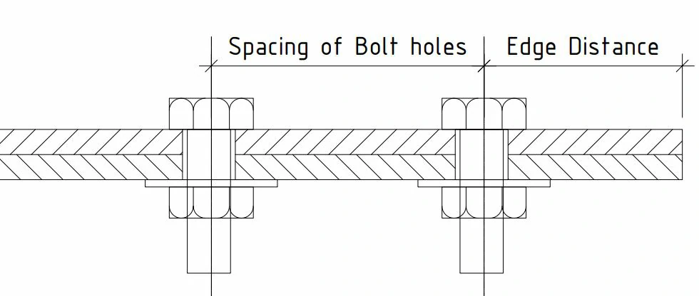
Minimum Edge Distance of Bolt Holes
Minimum edge distance is measured from the centre of a standard bolt hole to the edge of the connected part. The required distance applies in any direction and must satisfy the applicable value in AISC Table J3.4 or Table J3.4M, unless a different requirement applies under Section J3.10.
For oversized and slotted holes, the required edge distance is determined by adding the applicable increment, C₂, to the minimum edge distance required for a standard hole. The applicable C₂ value is provided in AISC Table J3.5 or Table J3.5M.
| Hole type | Minimum edge-distance requirement |
|---|---|
| Standard hole | Applicable value from Table J3.4 or Table J3.4M |
| Oversized hole | Standard-hole requirement plus applicable C₂ |
| Slotted hole | Standard-hole requirement plus applicable C₂ |
The values in the AISC tables are based on standard fabrication practices and workmanship tolerances. However, the final connection design must also satisfy the applicable requirements for bearing, tear-out, net-section rupture, and other relevant limit states. Edge distances smaller than one bolt diameter generally require approval from the engineer of record.
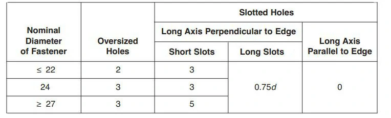
Example Calculation for an M20 Bolt
According to AISC Table J3.4M, the minimum edge distance for an M20 bolt in a standard hole is 26 mm.
For oversized and slotted holes, add the applicable C₂ value from Table J3.5M:
| Hole type | Calculation | Minimum edge distance |
|---|---|---|
| Standard hole | 26 mm | 26 mm |
| Oversized hole | 26 + 2 | 28 mm |
| Short slot, long axis perpendicular to edge | 26 + 3 | 29 mm |
| Long slot, long axis perpendicular to edge | 26 + 0.75d = 26 + 15 | 41 mm |
| Long slot, long axis parallel to edge | 26 + 0 | 26 mm |
Here, d = 20 mm, the nominal diameter of the M20 bolt. The required edge distance for a slotted hole depends on the slot orientation relative to the connected-part edge.
Maximum Edge Distance and Longitudinal Spacing
The distance from the centre of any bolt to the nearest edge of the connected parts in contact shall not exceed 12 times the thickness, t, of the connected part under consideration, or 150 mm (6 in.), whichever is smaller.
AISC also limits the longitudinal spacing of fasteners connecting a plate and a shape, or two plates, that are in continuous contact. The applicable limit depends on the protection and corrosion condition of the connected members:
| Member condition | Maximum longitudinal spacing |
|---|---|
| Painted members or unpainted members not subject to corrosion | The lesser of 24t or 300 mm (12 in.) |
| Unpainted weathering-steel members subject to atmospheric corrosion | The lesser of 14t or 180 mm (7 in.) |
In these limits, t is the thickness of the connected part for maximum edge distance and the thickness of the thinner part for longitudinal spacing.
The longitudinal-spacing limits above do not apply to elements consisting of two shapes in continuous contact. The actual bolt arrangement must also satisfy the applicable connection-strength, bearing, tear-out, and detailing requirements of the adopted AISC Specification.
| Bolt diameter | Minimum edge distance |
|---|---|
| M12 | 18 mm |
| M16 | 22 mm |
| M20 | 26 mm |
| M22 | 28 mm |
| M24 | 30 mm |
| M27 | 34 mm |
| M30 | 38 mm |
| M36 | 46 mm |
| Over M36 | 1.25d |
Also, read: Advantages And Disadvantages Of Welded Joints
FAQs:
Q: What are the four types of bolt holes in structural steel?
The four types are standard, oversized, short-slotted and long-slotted. Standard holes provide normal bolt clearance; oversized and slotted holes allow additional assembly adjustment. Their use depends on connection design and specification requirements. Larger holes do not automatically increase strength, and slots do not automatically provide for structural movement.
Q: Which bolt hole is used for the column base plate?
Base plates commonly use oversized round holes to accommodate anchor-rod placement tolerances and column alignment. Slotted holes may be used when specifically designed. Hole sizes and suitable washers must follow separate base-plate design guidance, rather than the standard structural bolt-hole table.
Q: Does a larger bolt hole make the connection stronger?
No. A larger hole does not allow greater bolt tightening or automatically increase strength. Connection strength depends on the bolts, connected materials, hole geometry and connection design.
Q: Does the direction of a slotted hole matter?
Yes. For bearing-type connections carrying shear, the slot’s long axis generally needs to be perpendicular to the load. Slip-critical connections may permit other orientations, subject to the applicable specification and design requirements.
Q: Can I enlarge a bolt hole on site if the bolt does not fit?
Only under an approved repair procedure. Enlarging a hole can affect its classification, edge distance, washer requirements and connection performance. Refer the misalignment to the responsible engineer before making changes.
Q: Which holes are commonly used for anchor rods in column base plates?
Base plates commonly use oversized round holes to accommodate anchor-rod placement tolerances and column alignment. Slotted holes may be used when specifically designed. Follow separate base-plate guidance for hole sizes and suitable washers rather than automatically using structural bolt-hole dimensions
References & Standards
- American Institute of Steel Construction: Engineering FAQs—Connections, Bolt Holes.
- Research Council on Structural Connections: Specification for Structural Joints Using High-Strength Bolts (2020), Section 3.3.
- American Institute of Steel Construction: Engineering FAQs—Anchor Rods, Base Plates, and Embedded Plates, Sections 7.2.3–7.2.4.


