Structural drawings are the backbone of any construction project, serving as the detailed blueprints that guide the building process. Whether you’re working on a multi-storied building, bridge or culvert, creating precise and accurate structural drawings is essential to ensure the safety, stability, and longevity of the structure. This article walks you through the step-by-step procedure for preparing structural drawings, from initial planning to finalization.
What are Structural Drawings?
Structural drawings are sets of engineering drawings prepared by a certified engineer for designed buildings or any other structure which demands it. The sets of drawings should consist of every detail drawing of the structural components and building elements that are usually subjected to load.
Structural drawings are the sets of engineering drawings prepared for or intended to communicate the structural requirement for the design structure. The structure drawing will be supplementary to architectural drawing for the construction of buildings and they are different in their own aspect. Structural drawing, therefore, should be referred in conjunction with architectural drawings.
This is the last stage in the structural design by the structural engineer. The structural design and analysis are done for the given architectural design. It is very crucial to do a thorough study of the proposed architectural drawing before designing and analysing it. After designing and analysing one should start with drafting or preparing structural drawings. Otherwise, the design file should be handed over to the draft personnel for preparing the required drawings.
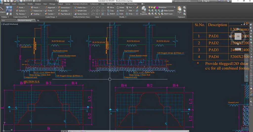
When is the Structure Drawing Prepared?
The structure drawing is demanded by those structures that require structural analysis and design to graphically represent the accepted design along with design calculation or procedure on paper. Structures like, bridges and culvert demands the structure drawing. Building construction also requires structure drawings.
Planning and Conceptual Design
The first step in preparing structural drawings involves thorough planning and conceptual design. This phase is crucial as it lays the foundation for the entire project.
Site Analysis: Understand the site conditions, including soil type, topography, seismic activity, wind load, and environmental factors. Therefore, understanding these aspects helps in determining the appropriate structural design.
Architectural Design: Work closely with architects to finalize the building’s layout, height, and functional spaces. The architectural design provides the framework within which the structural components will fit.
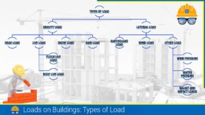
Load Calculations: Determine the loads the structure will carry, such as dead loads (self-weight of the structure), live loads (occupants, furniture), and environmental loads (wind, earthquake, snow, etc.). Accurate load calculations are critical for ensuring the structure’s safety and performance.
Structural Analysis
Once the conceptual design is in place, the next step is to analyze how the structure will respond to the loads it will carry.
Material Selection: Choose the appropriate construction materials, whether it’s concrete, steel, or composite materials. The choice of material will influence the design and detailing of structural elements.
Load Analysis: Using advanced software like ETABS, STAAD Pro, or SAP2000, perform structural analysis to simulate how the building or bridge will behave under different loading conditions. This analysis helps in identifying potential issues and refining the design.
Compliance with Standards: Ensure that the design adheres to relevant building codes and standards, such as ACI, Eurocode, or IS codes. Compliance is essential for obtaining approval from regulatory authorities and ensuring the safety of the structure.
Detailed Structural Design
After the structural analysis, it’s time to prepare a detailed design of individual components.
Designing Structural Components: This involves calculating the size and reinforcement details for beams, columns, slabs, and foundations. For bridges, the design includes decks, girders, piers, and abutments.
Lateral Force-Resisting Systems: In areas prone to seismic activity or high winds, it’s important to design shear walls, bracings, or other lateral force-resisting systems to ensure the structure can withstand these forces.
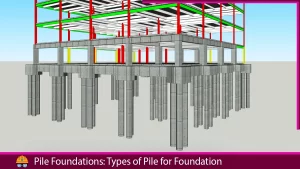
Foundation Design: The foundation is critical to the stability of the structure. Depending on soil conditions and building loads, choose the appropriate type of foundation, such as isolated footings, raft foundations, or pile foundations.
Preparation of Structural Drawings
With the detailed design complete, the next step is to create the structural drawings, which will be used during construction.
General Arrangement (GA) Drawings: These drawings include floor plans, elevations, and sections, providing a comprehensive overview of the structure’s layout and vertical relationships.
Reinforcement Detailing: This involves creating rebar drawings that specify the size, spacing, and placement of reinforcement bars in concrete elements. A Bar Bending Schedule (BBS) accompanies these drawings, detailing the specifications for cutting and bending the rebar.
Connection Details: In steel structures, connection details are critical. These drawings show the connections between beams, columns, base plates, and anchor bolts.
Composition of Structural Drawings
The drawing sheet sets should consist of all the necessary drawings. However, the following are the general requirements for the compilation of the structural drawings of the R.C. Structure.
- Structural Drawing note
- Foundation and footing drawings
- Column layout and section drawings
- Beam layout and section drawings
- Floor slab layout and section drawings
- Staircase plan and section drawings
- Truss layout and section drawings
- Wall section details
- Other documents such as designer certificate, design worksheet/calculation/result must be attached
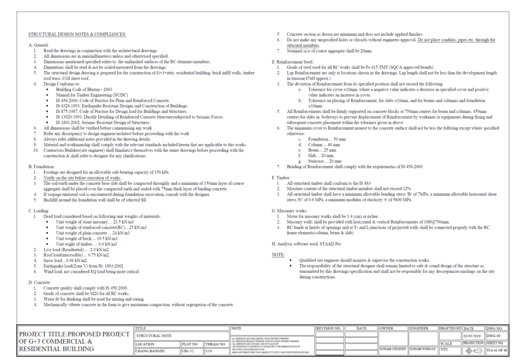
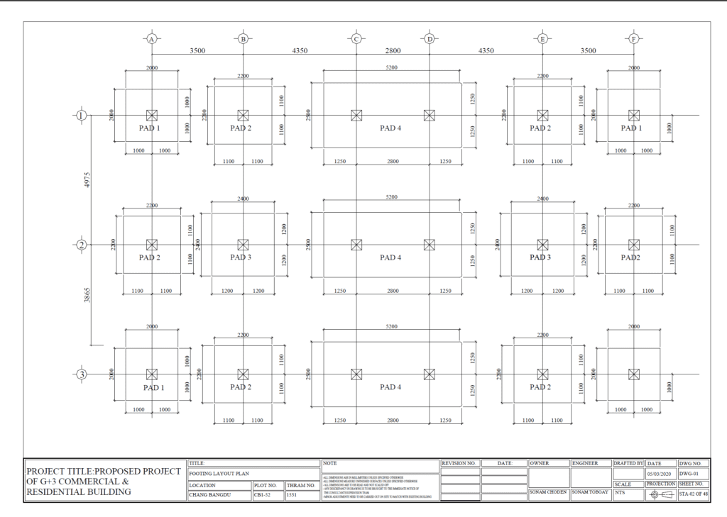
As per the Building Regulation of Bhutan 2018
The structural drawings shall include the following:
- Notes:
- Calculation note-sheets
- Design codes (used for designing)
- material specification/ properties of the materials
- The geotechnical report for soil (soil bearing capacity) is attached with the drawing
- levels, measurement units and scale of the drawings
- A foundation plan, foundation details, including the depth of the foundation and plinth level and in the case of foundations on different levels – retaining details
- Details of the beam and slab layout plan of each floor, showing clearly the staircase opening, shaft opening and any other openings and depressions;
- Concrete and reinforcement details of foundation, beams, slab, staircase, lintel, cornice, projections, zhu and Rabsel, wall and other features;
- Truss elevations and connection details showing the holding-down details;
- Details and location of separation gaps;
- Details of splice locations and splice length for beams, columns, slab and staircase;
- For load-bearing walls – details of plinth band, lintel band and roof band, including vertical bars at corners, opening jambs and wall junctions; and
- The dimensions of all structural members, including:
- Anchorage of beam bars in an existing beam-column junction; and
- column ties and beam stirrup details.
Also, read: Structure Drawing Detailing for Reinforced Concrete Structures
Certification of The Drawings
Like other technical drawings, the structural drawing prepared should be certified by the designer for readiness and use on the construction site. However, the drawing must be approved by the government office (municipal or city corporation) or relevant authority before the execution of the works.
The drawing shall be signed by the owner, designer and drafter (if there). The owner’s signature is done to accept the prepared drawing. The person who prepares the drawing must sign it with the contact details such as e-mail ID, contact number, and address. The designer’s certificate must be attached with drawings.
Advantages of Structural Drawings
There are several advantages of structural drawings as mentioned below: –
- Clear Communication:
- Structural drawings provide a clear and detailed visualization of a project’s design concept, ensuring that all parties involved—architects, engineers, contractors, and clients—have a precise understanding of the structure.
- These drawings use standardized symbols and notations, which help in communicating complex information effectively, reducing the chances of misunderstandings or errors during construction.
- Accuracy in Construction:
- Structural drawings contain detailed specifications, including dimensions, materials, and the exact placement of structural components, ensuring accuracy in construction.
- They incorporate load calculations, which help in determining the strength and stability of the structure, ensuring that it can withstand the required loads.
- Efficient Project Management
- Detailed and accurate drawings allow for precise material takeoffs, which assist in budgeting and cost estimation, helping to avoid overordering or underordering of materials.
- These drawings aid in project scheduling, helping to optimize timelines and resource allocation.
- Quality Control:
- During and after construction, structural drawings serve as a verification tool to ensure that the work has been executed as per the design, which is crucial for quality assurance.
Also, read: 2 Methods of Estimate For Buildings.
Disadvantages of Structural Drawings
There are many disadvantages to structural drawings: –
- The drawing reading is not easy for the common people or untrained personnel.
- Not all the drawings are identical to each other and have different representations which may confuse the drawing reader
- It is time-consuming to prepare the structural drawing for untrained personnel.
Also, read: Scale In Engineering Drawings
FAQs:
Q: How long does it take to make a complete set of structural drawings?
Answer: Making a complete set of structural drawings dramatically depends upon the type of structure, number of floors, area of the structure, and design of the structure. It is also dependent on how good the designer and drafter are at preparing the drawings. However, these days, due to the availability of CAD software, has dramatically reduced the time for preparing neat and standard drawings for assigned projects. Only very few people (engineers) are traditionally preparing the drawing using the T-square and drawing board.
It takes a month or 2 to prepare a complete set of structural drawings (including concrete and reinforcement details for every member and building element) depending upon the magnitude of the project works.
Q: How many types of structural drawings are there?
Answer: Basically, structural drawings are one type of drawing prepared by the structural engineer. However, structural drawings can be classified into two categories namely concrete work drawings and reinforcement work drawings. There are other classifications of structure drawing as well. These are Standard details drawings, Typical drawings and Record drawings.
Q: What is the difference between Engineering Drawing and Structural Engineering Drawings?
Answer: An engineering drawing is a type of technical drawing that is used to convey information about an object. Whereas, structural drawing is a representation of the design aspect of the structure like buildings, bridges, tunnels etc…
Q: Who regulates the technical drawings?
Answer: The government agency is the one to check the drawings as per the regulations published by the regulatory authority.
Q: Who can prepare structure drawings?
Answer: A person with a very good knowledge of the structure or a certified structural engineer must prepare the drawing to eliminate the mistakes and errors in the drawings. However, a person can make the drafter prepare the drawings but must guide all the design requirements as per the design or analysis performed either manually or with CAD software.
References:
- Bhavikatti, S.S. (2016). Design of RCC Structural Elements (RCC Volume-II) (2nd ed.). New Age International (P) Ltd., Publishers
- Chandra, Dr. R. (2018). Reinforced Concrete Structure(Limit State Design) (ISBN-13: 9788189401399): A Text-book of Reinforced Concrete Structures (3rd ed.). Standard Book House Since 1960.
- Duggal. S.K. (2014). Limit State Design of Steel Structures (2nd ed.). McGraw Hill Education (India) Private Limited
- Wikipedia contributors. (2024, March 20). Structural drawing. Wikipedia. https://en.wikipedia.org/wiki/Structural_drawing↗
- Bureau of Indian Standards. (2016). Ductile Design and Detailing of Reinforced
Concrete Structures Subjected to Seismic Forces: —Code of Practice (IS 13920: 2016) (First Revision). Bureau of Indian Standard (BIS).
![]()



Great article on preparing structural drawings! I appreciate how you broke down the various steps in such a clear and methodical way. It’s always crucial to ensure that the foundation is laid out properly, especially when working on projects with intricate details like stucco finishes. I’ve found that when working with stucco, it’s particularly important to account for the structural support behind the finish, as it adds significant weight. Your points about ensuring accurate dimensions and clear annotations resonate with that, as stucco can sometimes add unexpected challenges in terms of load-bearing.
Do you have any advice on how structural engineers can best communicate with contractors regarding exterior finishes like stucco to avoid missteps during the build?