Buildings are subjected to several types of loads. Those loads are classified into two main classifications of loads and they are:
- Gravity loads
- Lateral loads
Gravity loads, which are also known as vertical loads, are generated by the earth’s gravitational pull and exert force in a downward direction. These loads encompass everything contained within a building, such as building materials, components, people, furniture, equipment, rainwater, and snow. Gravity loads are further classified as dead, live, snow, and rain loads.
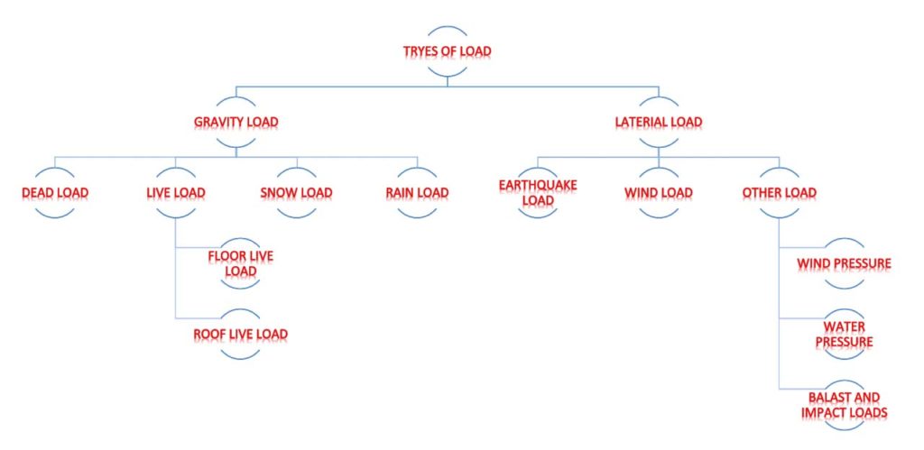
Lateral loads, Buildings are subjected to lateral loads mainly due to wind and earthquakes. These loads are generated horizontally or in directions other than directly downward. For instance, wind can cause horizontal forces on walls and upward vertical forces (suction) on flat roofs. Earthquakes, on the other hand, create horizontal forces in buildings, though a minor amount of sheer force may also occur. Other types of lateral loads include earth pressure on basement walls, water pressure on tank walls, and loads caused by moving vehicles, equipment, or blasts.
Dead Loads
In a building, dead loads remain constant and do not fluctuate with time. These loads consist of the weights of various materials and components that constitute the structure. The computation of a component’s dead load involves multiplying its volume by the density of the material. Since the densities and dimensions of components are reasonably accurate, estimating dead loads in a building can be done with more certainty than other types of loads. The densities of frequently used materials are provided in IS 875 (Part-1).

A dead load of a building component encompasses its self-load as well as the dead loads of all other components it supports. For instance, the dead load on a column comprises not only the weight of the column itself but also the dead load imposed on it. In Figure 1, the dead load on a column includes the weight of the column and the dead load from the beams and slab resting on it. Similarly, the dead load on a beam is the weight of the beam and the dead load from the slab it supports. Only the self-weight of the slab constitutes the dead load on the slab. However, if the slab supports a floor finish, ceiling, light fixtures, or plumbing and electrical pipes, their weights must also be included in the dead load acting on the slab.
Live Loads
While the dead load is constant and remains permanently on the structure, the live load is characterized as a load whose magnitude and positioning vary over time. These loads arise from the weights of people, furniture, movable equipment, and stored materials, as well as animals if the building accommodates them. Figure 1 demonstrates that live loads are further subdivided into different categories.
- Floor live load
- Roof live load
Floor Live Load
The live load imposed on a floor is influenced by the purpose and use of the building. For this reason, it is also referred to as the occupancy load, and it varies depending on the type of occupancy. For example, the floor live load for a library stack room is greater than the floor live load for a library reading room, which, in turn, is greater than the floor live load for an apartment building.
Floor live loads are calculated by summing up the loads generated by all people, furniture, and movable equipment that might result from the specific occupancy. To ensure safety, the structure is designed to handle the highest possible live load that could be imposed on it, taking into account the worst expected scenario.
Building codes provide tables of floor live loads for a variety of structures such as individual dwellings, hotels, apartment buildings, libraries, office buildings, and industrial structures. These floor live loads have already been established and are specific to each occupancy. IS 875 (Part-2) is established for live load in India for various occupancies.
It is usually assumed that floor live loads are distributed uniformly across the entire floor area and are measured in kilo Newton per square meter (kN/m2). However, a perfectly uniform distribution is rarely achieved in real-world situations. To address this issue, building codes suggest that the impact of live load concentration be examined for occupancies where it could potentially impact the design.
These occupancies are parking garages (where loads are concentrated on vehicle tires), libraries, offices, schools, and hospitals. Apartments, hotels, individual residences, assembly buildings (auditoriums, concert halls, grandstands), and exit areas of all buildings do not require investigation for concentrated loads.
For example, as per the IS 875 (part-2) the minimum floor live load for a library stack room is 6kN/m2, for a library reading room is 4kN/m2, and for a residential building is 2-3 kN/m2. It should be noted that these are the minimum floor Live loads for which the building must be designed. Even if the actual live load on a floor is smaller, the structure must be designed for the minimum live load specified by the building code.
| Rooms | Udl | Concentrated Load |
|---|---|---|
| Living rooms and bedrooms | 2 kN/m2 | 1.8 kN |
| Kitchen | 3 kN/m2 | 4.5 kN |
| Dinning rooms | 4 kN/m2 | 2.7 kN |
| Office rooms | 2.5 kN/m2 | 2.7 kN |
| Storerooms | 5 kN/m2 | 4.5 kN |
| Balconies | 4 kN/m2 | 1.5 kN |
| Bathrooms and toilet | 2 kN/m2 | – |
| Corridors, passages, staircase, etc. | 3 kN/m2 | 4.5 kN |
| Indoor game rooms | 3 kN/m2 | 1.8 kN |
Roof Live Load
The weight of personnel performing repairs and any temporary storage of construction or repair materials and equipment on the roof is considered when calculating the live load on a roof. Generally, the roof live load is given as 1.5kN/m2 with access provided for the above task to carry on and 0.75kN/m2 for a roof without access. This is applicable for roofs that will not be used as a floor in the future.
If the building is expected to be extended vertically in the future, the roof live load should be based on the floor live load for the expected future occupancy. In addition, if the roof is intended to be used as a landscape, the weight of the growth medium and landscaping elements must be considered as part of the dead load on the roof.
| Sl.No. | Types of Roof | Imposed load measured on plan area | Minimum imposed load measured on plan |
|---|---|---|---|
| 1. | Flat. sloping or curved roof with slopes up to and including 10 degrees | ||
| 1. Access provided | 1.5 kN/m2 | ||
| 2. Access not provided except for maintenance | 0.75 kN/m2 | 1.9 kN uniformly distributed over any span of 1-metre width of the roof slab and 4.5 kN uniformly distributed over the span of any beam of truss or wall. | |
| 2 | Slopping roof with slope greater than 10 degrees | For roof membrane sheets or purlins- 0.75 kN/m2 for every degree increase in slop over 10 degrees | Subject to a minimum of 0.4 kN/m2 |
| 3 | Curved roof with slope of line obtained by joining springing point to the crown with the horizontal, greater than 10 degrees | (0.75-0.52 \( \alpha \) kN/m2 where, \( \alpha\;=\frac hl \) \( h \) = height of the highest point of the structure measured form its springing: and \( l \) = chord width of the roof if the single curved and shorter of the two sides if doubly curved. | Subject to a minimum of 0.4 kN/m2 |
Environmental Loads
Earthquake Load
The devastation caused by earthquakes, which can claim numerous lives and damage infrastructure, makes them one of the most fearsome natural disasters. The Turkey-Syria earthquake that occurred on February 6, 2023, with a magnitude of 7.8, reportedly claimed the lives of 57,000 people. Regardless of where an earthquake happens, it quickly becomes global news. Despite this, the risk of loss of life from earthquakes is generally lower than it used to be, particularly in developed countries, due to increased awareness and knowledge of how to construct structures that are resistant to earthquakes.
Earthquake load refers to the force or stresses that are exerted on a structure during an earthquake. It is caused by the ground motion generated by seismic waves, which can cause the building to move and sway, leading to stresses and deformation in its structural elements. The earthquake load intensity depends on a variety of factors, including the earthquake’s magnitude and duration, the distance from the epicentre, and the characteristics and condition of the soil and rock beneath the building. Designing structures that can withstand earthquake loads is crucial to ensure their safety and prevent damage or collapse during an earthquake.
The type of soil, the size, and the method of construction, as well as the duration and severity of ground motion, all affect how the building responds to ground vibration. The details of such estimates for structures standing on soils that will not noticeably settle or slide due to an earthquake are provided in IS 1893-2016.
Also, read: Stirrups: The Shear Reinforcement Bar.
Wind Loads
Though wind loads are mainly horizontal, they can also create an upward force on flat or low-sloped roofs. To withstand this upward force, buildings must be anchored to their foundations. On the other hand, to withstand horizontal wind loads, anchorage to foundations and the use of stiffening elements are required. The stiffening elements are commonly known as wind-bracing elements.
The requirement for wind bracing in a building is similar to the need for diagonal or sheet bracing in a bookshelf. A bookshelf made up of multiple shelves mounted on two side supports can bear the weight of the books, but it will not be stable. When subjected to horizontal forces from any direction, it will move sideways or become unstable. Racking of the bookshelf can be prevented by diagonally bracing one of its faces. An alternative method of stiffening the structure over the entire face instead of diagonal braces. Sheet bracing generally provides greater lateral stiffening than diagonal bracing.
Therefore, there are several methods of wind bracing provided to the buildings, depending on the functional and aesthetic constraints of the building and the magnitude of wind loads. Because wind loads increase with the height of a building, stiffening the building against wind loads becomes increasingly important as the height of the building increases. In fact, the design of tall buildings is heavily dominated by wind-bracing requirements.
Wind loads typically act horizontally, and small and low-rise buildings do not usually account for such loads in their design, but they are considered in the case of high-rise structures. According to IS: 875 (Part 3), the design wind load takes into account factors such as wind speed, topography, location, and shape of the building. The velocity of the wind at a specific height, Vz, can be determined using a formula.
VZ=k1k2k3Vb
where,
k1 = Risk coefficient
k2 = Coefficient based on terrain, height, and size of the structure
k3 = Topography factor
Vb = Basic wind speed (m/sec)
The design wind pressure (pz) at a height z is given as
\( p_z\;=0.6V_z^2 \)
where pz is in N/m2 at height z and VZ is in m/sec. Up to a height of 30 m, the wind pressure is considered to act uniformly. Above 30 m height, the wind pressure increases.
Snow Load
The design of a roof is based on the greater of two loads: the roof live load or the snow load. This is because when a roof is fully loaded with snow, it is unlikely that repair or construction crews will access it, thereby imposing an additional live load. The snow load is also expressed in terms of the horizontal projected area of the roof, similar to the roof live load.
The minimum snow load on a roof area or any other area above ground which is subjected to snow accumulation is obtained by the expression,
\( S=\mu S_0 \)
where,
S = Design snow load on the plan area of the roof
\( \mu \) = Shape coefficient, and
S0 = Ground snow load.
The ground snow load at any place depends on the critical combination of the maximum depth of undisturbed aggregate cumulative snowfall and its average density. The shape coefficient depends on the shape of the roofs and for some of the common shapes the code gives these coefficients. When the slope is more than 60 degrees the snow load is not considered.
The roof should be designed for the actual load due to snow or for the imposed load, whichever is more severe.
Also, read: Development Length For Reinforcement Bar | Anchorage Length | Lap Length | Formula | Calculation
Rain Load
Although roofs are designed to have adequate drainage so that no accumulation of water occurs, loads resulting from the accidental accumulation of melted snow or rainwater must be considered as a possibility. Drains may be blocked by windblown debris or hail aggregating on the roof or the formation of ice dams near the drains.
Long-span, relatively flat roofs are particularly vulnerable to rainwater accumulation because, being flexible, they deflect under the weight of water. This deflection leads to yet more accumulated water, causing additional deflection, which increases accumulation. If adequate stiffness is not provided in the roof, the progressive increase of deflection can cause excessive load on the roof. Water accumulation has been the cause of the complete collapse
of several long-span roofs.
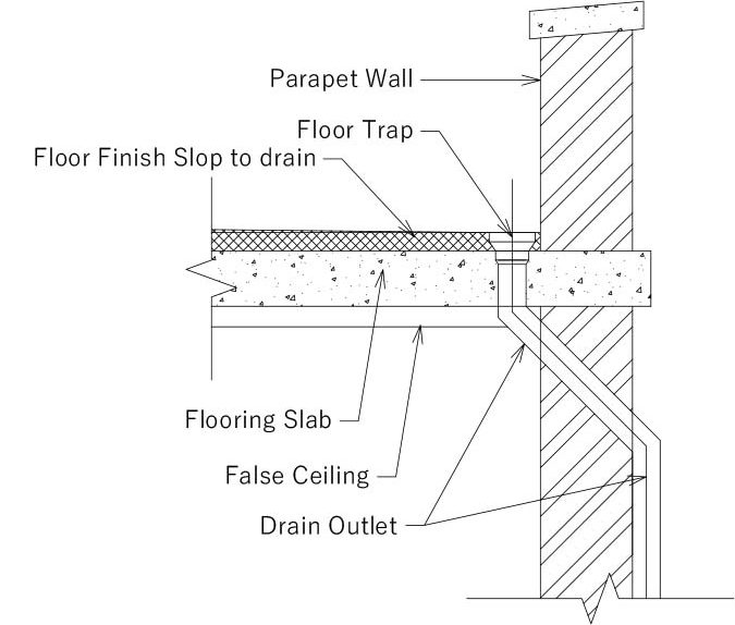
be provided with a drain outlet
Generally, roofs with slopes greater than 1 to 12 m (5-degree slope) are not subjected to accumulated rainwater unless roof drains are blocked. Building codes mandate the minimum slope required for roofs to be 5 degrees, which, apart from providing positive drainage, also helps to increase the life and improve the performance of roof membranes.
To avoid the accumulation of rainwater on the roof, a primary and secondary drain must be provided. However, the secondary drain is provided only in the case the primary drain gets blocked, it should drain out accumulated water. The secondary drain is provided 25mm (1 inch) above the primary drain and Figure 3 shows the general assembly of the drain on the parapet roof.
The rain load is not mandatory calculated for the slopy roof as it does not account for the accumulation on the roof. However, for a flat roof, the following formula is used to calculate the rain load.
\( R_L=5.2\times\left(D_s+d_h\right) \)
Where,
\( R_L \) is the rain load (kN/m2 or psi)
\( D_s \) is the depth of the water up to the secondary inlet of drainage (mm/inches)
\( d_h \) is the depth of the water above the secondary inlet of drainage (mm/inches)
Also, read: How To Calculate Chair Bars Requirements?
References:
- M. Madan, S. Walter, A. Diane, (2009). Building Construction, Principles, Materials, and Systems, Pearson Education
- Parasher A. (2022, October 4). Types of Loads on Structures. BYJU’S Exam Prep. https://byjusexamprep.com/types-of-loads-i#Types_of_Loads__Wind_Loads
- American Society of Civil Engineers. (2016). Minimum design loads and associated criteria for buildings and other structures (ASCE/SEI 7-16). Reston, VA: American Society of Civil Engineers.
- Bureau of Indian Standards. (1987). IS: 875 (Part 1 Dead Load) – 1987: Code of practice for design loads (other than earthquake) for buildings and structures. New Delhi: Bureau of Indian Standards.
- Bureau of Indian Standards. (1987). IS: 875 (Part 2 Imposed Load) – 1987: Code of practice for design loads (other than earthquake) for buildings and structures. New Delhi: Bureau of Indian Standards.
- Bureau of Indian Standards. (1987). IS: 875 (Part 3 Wind Load) – 1987: Code of practice for design loads (other than earthquake) for buildings and structures. New Delhi: Bureau of Indian Standards.
- Bureau of Indian Standards. (1987). IS: 875 (Part 4) – 1987: Code of practice for design loads (other than earthquake) for buildings and structures. New Delhi: Bureau of Indian Standards.
![]()




![Read more about the article Joints for Concrete Pipes [pdf]](https://civilengpro.com/wp-content/uploads/2022/11/JOINTS-FOR-CONCRETE-PIPES-300x169.jpg)
