Manholes are a common sight in urban areas, but despite their prevalence, many people may not fully understand what they are or how they work. In this article, we’ll explore the basics of manholes, including their purpose, types, location, and components.
What is a Manhole?
Essentially, it’s a vertical access point to an underground utility network, such as a sewer or stormwater system. Manholes are typically cylindrical, and they can range in size from small enough for a single person to access to large enough for vehicles or equipment to enter.
It is defined as the masonry or R.C.C chambers, constructed at suitable intervals along the sewer lines, for providing access to them (Garg. p131).
Purpose of Manhole:
The primary functions are as follows:
- To provide access for inspection, cleaning, and removal of any obstructions present in the sewage line.
- To facilitate the joining of sewers, change of direction, or alignment of sewers.
- To provide ventilation for the underground sewage system through its perforated cover, which allows foul gases to escape.
- To enable the installation of sewer lines in conventional lengths.
Types of Manholes:
There are three primary types and they are categorized based on their depth:
Shallow Manhole:
A shallow manhole, also known as an inspection chamber, is typically constructed at the beginning of a branch sewer or in areas that are not expected to have heavy traffic. It usually has a depth ranging from 0.7 to 0.9 meters and is equipped with a lightweight cover at the top.
Normal Manhole:
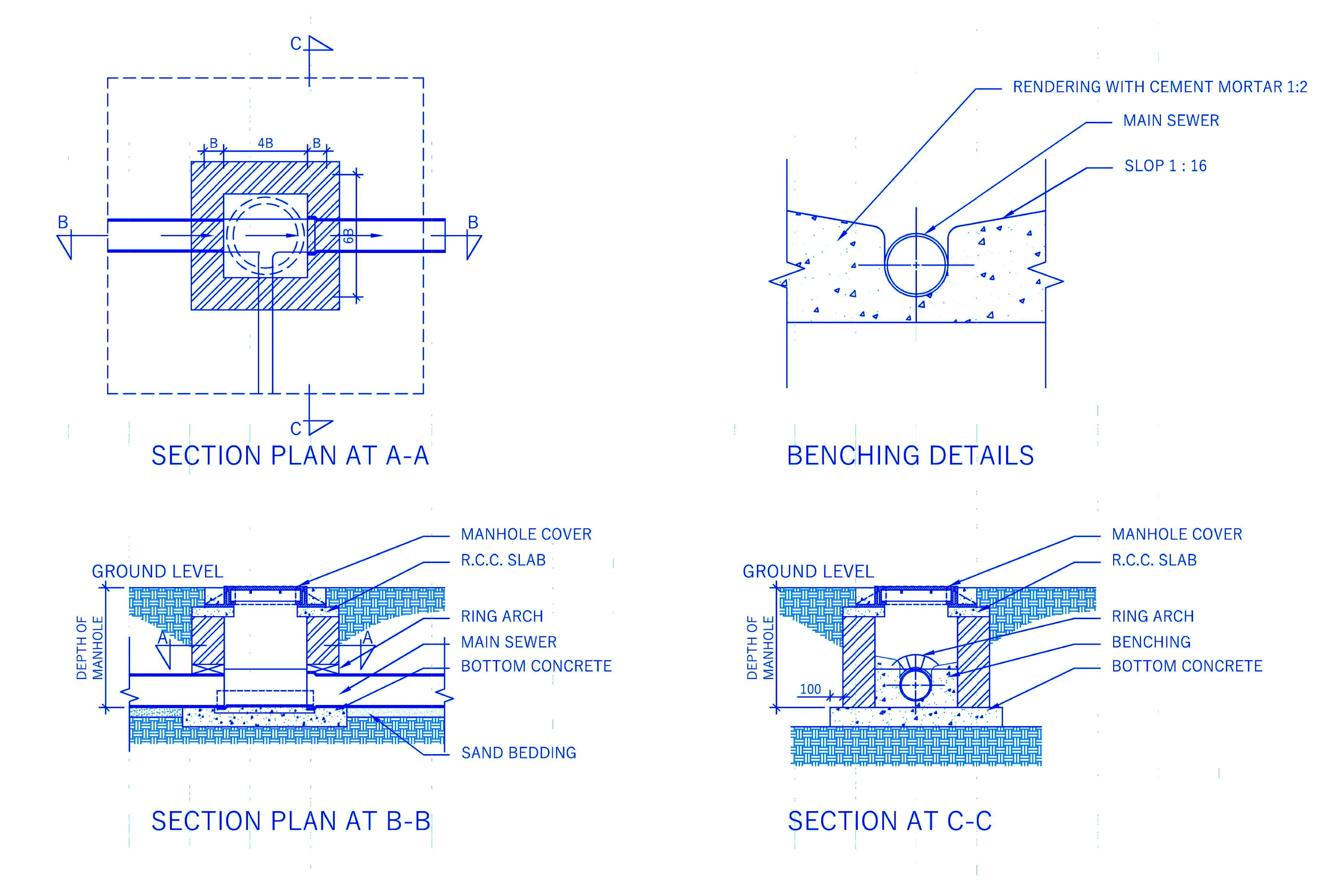
Typically, a normal manhole is constructed with a depth of 1.5 meters and can have either a square (1m x 1m) or rectangular (1.2m x 1m) cross-section. Unlike a deep manhole, the section remains constant throughout its depth and does not change. A heavy-duty cover is installed on top for safety.
Deep Manhole:
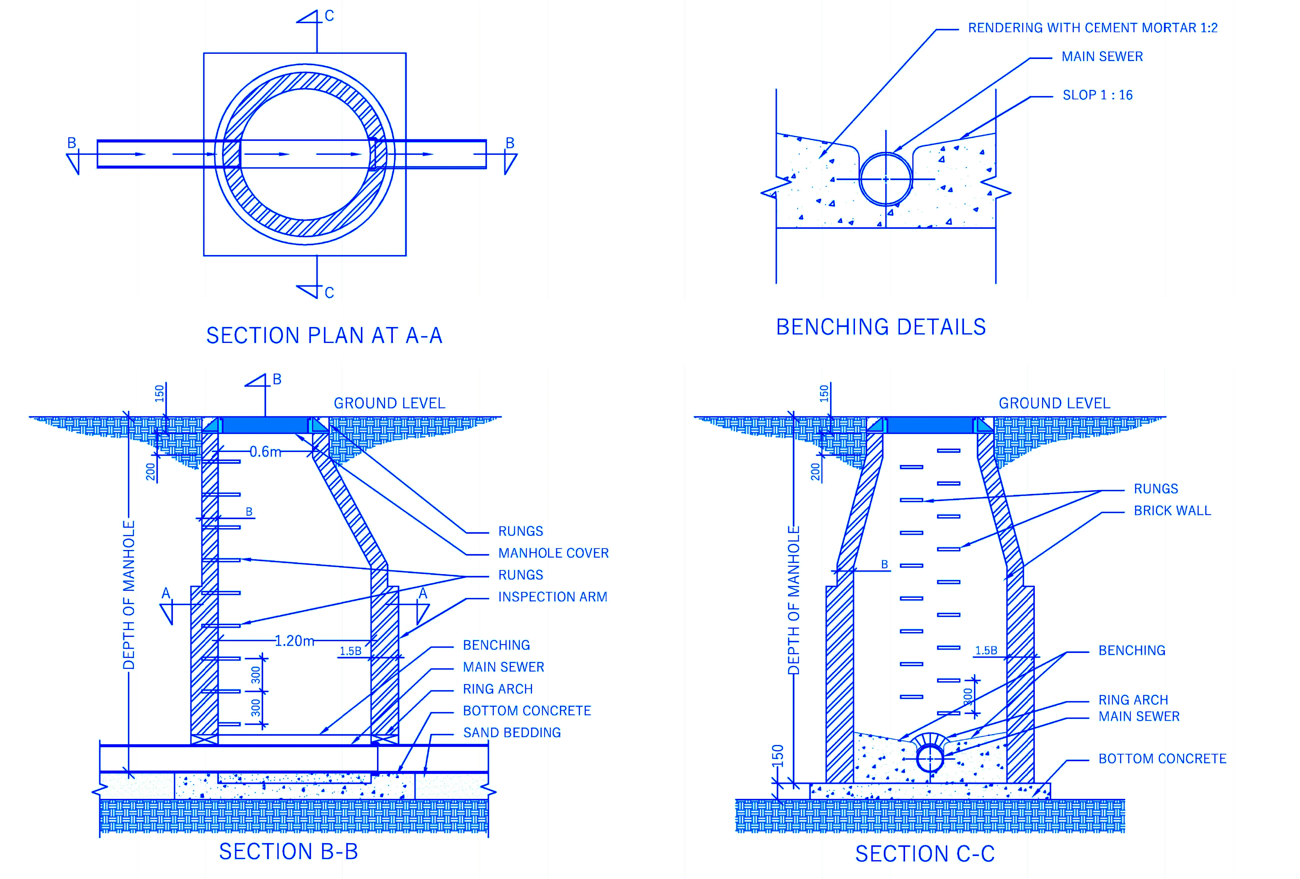
A deep manhole is defined as having a depth greater than 1.5 meters. The section of a deep manhole is typically designed to change, with an offset provided in the upper portion, as depicted in Figure below. Rungs or other means of descent are often incorporated into the design to facilitate entry and exit from the manhole. A heavy cover is installed on top of the manhole for safety reasons.
Location:
They are generally provided at every bend, junction, change in gradient or change of sewer diameter. If there are no obstetrical or difficulties, they are laid in a straight line with an even gradient.
Spacing:
The spacing of manholes in a sewage system refers to the regular intervals between two adjacent manholes in a straight line. However, the spacing between manholes is heavily dependent on the diameter of the sewer. IS 4111-1967 (part-1) provides guidelines for the recommended spacing between manholes, as shown in the table below:
| Sl.No. | SIZE OF THE SEWER | RECOMMENDED SPACING ON STRAIGHT LINE |
|---|---|---|
| 1. | Dia up to 0.3 m | 45 m |
| 2. | Dia up to 0.6 m | 75 m |
| 3. | Dia up to 0.9 m | 90 m |
| 4. | Dia up to 1.2 m | 120 m |
| 5. | Dia up to 1.5 m | 250 m |
| 6. | Dia greater than 1.5 m | 300 m |
Construction and Components of Manhole:
Typical details of a manhole are shown in the figure below and its various components are briefly discussed as follows:
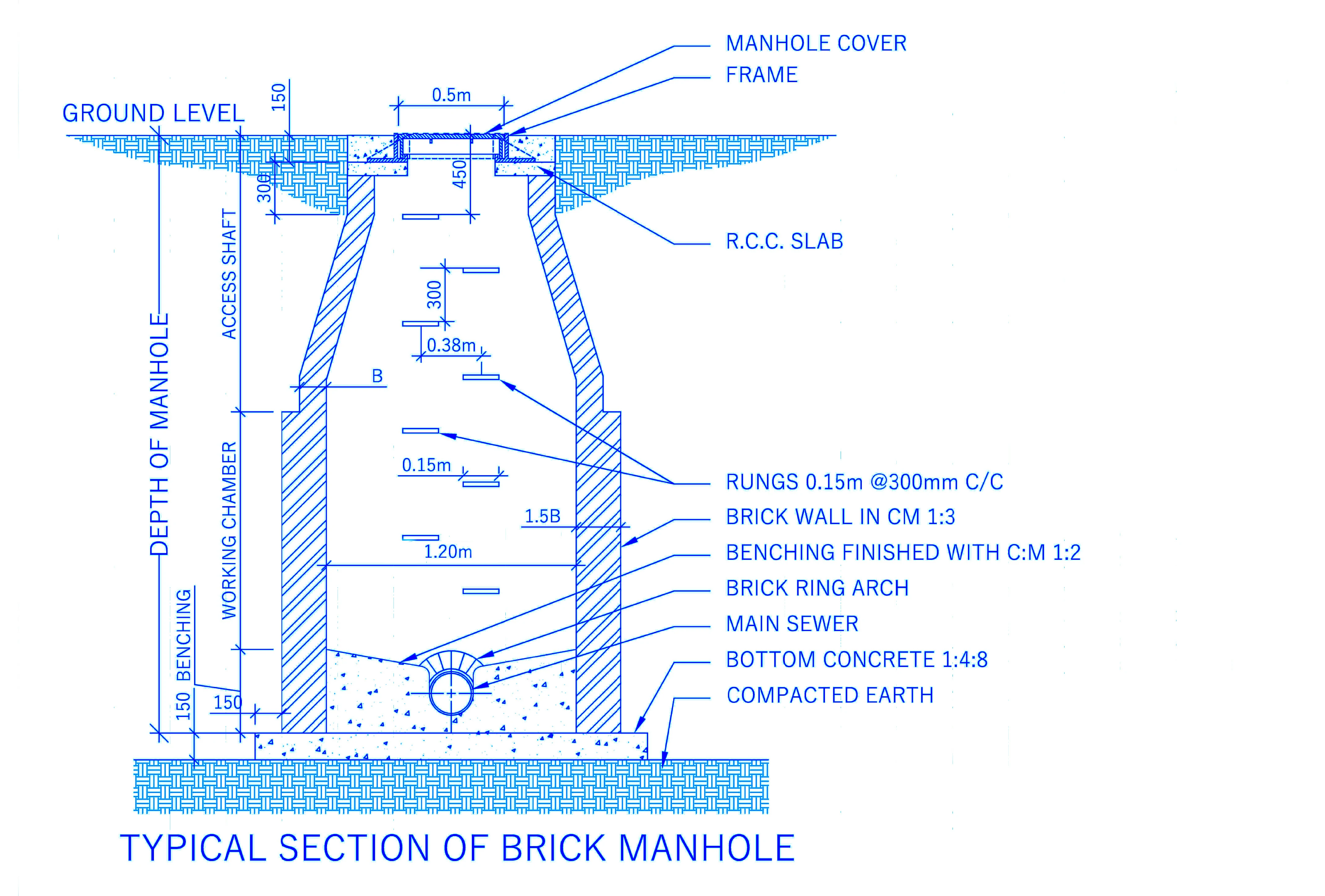
Access Shaft: This section refers to the upper portion of a deep manhole. For a rectangular manhole, the minimum size requirement is approximately 0.75m x 0.6m, while for a circular manhole, the minimum diameter should be around 0.6 to 0.7m. The depth of this portion is dependent on both the overall depth of the manhole and the required height of the working chamber.
Working Chamber: The lower section of a manhole is referred to as the working chamber, as it provides sufficient space for inspection and cleaning operations. The minimum size requirement for a rectangular manhole is 1.2m x 0.9m, while for a circular manhole, the minimum diameter should be 1.2m. Additionally, the height of the working chamber should be greater than 1.8m.
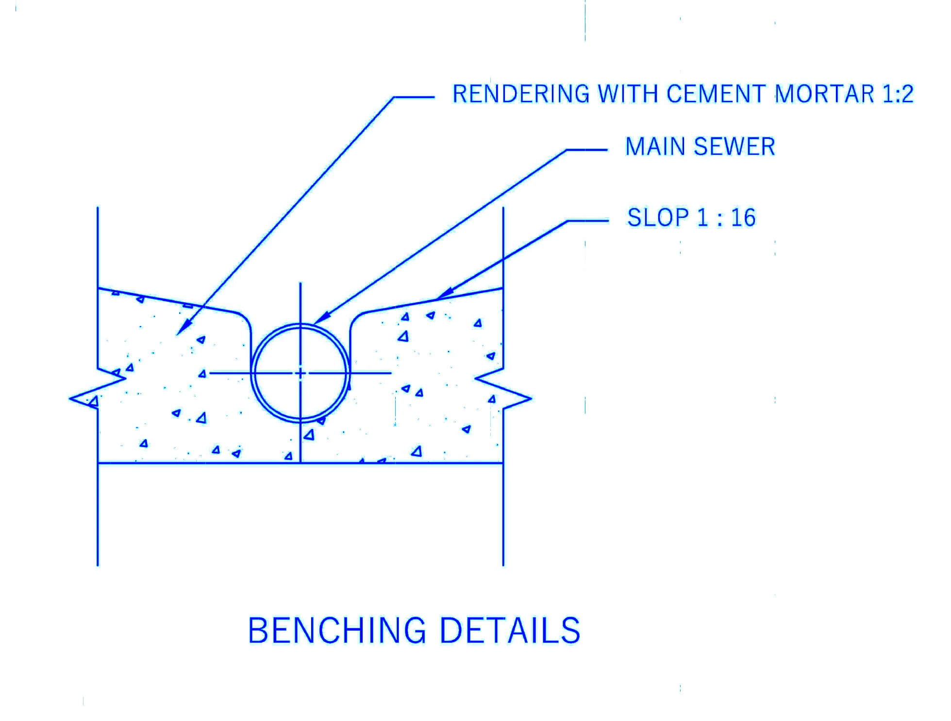
Benching: It refers to the bottom or inverted portion of the manhole which is constructed in cement mortar. The benching is usually constructed as a semicircular or a U-shape channel with sides sloping (1 in 6) towards it as shown in benching detail in the drawing. It facilitates the entry of sewage into the main sewer. Channel will ease the faculty of the manhole when the branch sewer meets with the main sewer having the same level.
Side Walls: The side walls are constructed with bricks masonry, stone masonry or R.C.C. The thickness of the R.C.C. walls is much less compared to masonry walls (brick and stone masonry) and is designed by the usual structure method of analysis. The wall shall be plastered with a 15mm thick layer of cement mortar with a ratio of 1:3, both on the inside and outside. Where there is a presence of sub-soil water, a richer cement mortar must be used to plaster for both masonry and plastering work. A radius of 7.5 cm shall be applied to all angles, and the inner surfaces that are rendered shall have a durable impermeable texture achieved using a steel trowel.
The minimum thickness of the brick wall should be 225mm. However, the approximate thickness may be computed by using the empirical thumb rule:
t=10+4d
where,
t = thickness of the brick wall
d = Depth of excavation
Rungs: Rungs commonly known as Ledder or steps are generally provided for descending and ascending from the manhole while carrying out inspection and cleaning operations. They are usually provided in all manholes over 80cm in depth and shall be made of cast iron. They should be equally spaced at 300mm and the top is 450mm from the cover and the lowest is more than 300mm from the benching. They are staggered in two vertical runs that may be 360mm apart horizontally.
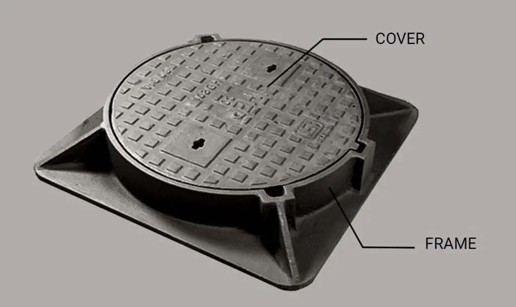
Cover and Frame: Cast iron cover and a frame of the same material are provided at the top of the manhole. The thickness of the frame is 20 to 25 cm, and its base is about 10 cm wide. it is firmly embedded in the pavement and the cover rests in the groove which is kept inside the frame. The cover may be circular or rectangular with a dimension of 0.5 to 0.6 m and 0.6 X 0.45 m respectively. The weight of the cover and frame varies from 90 to 270 kg.
One feature of the cover is that its top surface is rough to avoid slipping off the person while walking over it. The cover should be placed with the arrow mark pointing to the flow direction of the sewer. To avoid any inconvenience to the traffic, the top level of cover must be flush with the road or pavement level.
Invert Level: It is the lowest part of the manhole. This level is of utmost importance, as it is established about a fixed reference point (specific datum), and specifically ensures that the water flows naturally towards its intended destination by utilizing the force of gravity.
Inlet and Outlet: Inlet and outlet refer to the points of entry and exit for the flow of water within a manhole. While there may be several inlets to a manhole, there is typically only one outlet. In certain cases, a bifurcation manhole may be used to divide the flow of water into separate downstream pipes.
Materials for Manhole
Manholes can either be constructed on-site or obtained as pre-made units for installation as required. Consequently, manholes can be fabricated using materials such as concrete, precast elements, fibreglass, and plastic, all of which are readily available options.
FAQs:
Q: What is a manhole?
Ans: It is an underground civil engineering structure that is built to allow access to utilities such as sewer and drainage systems. This enables the inspection, modification, cleaning, and maintenance of underground utilities to be carried out efficiently.
Q: What is the purpose of a manhole?
Ans: Its purpose is to provide access to underground utilities, such as sewer systems, drainage systems, and other infrastructure. It allows maintenance workers to inspect, clean, modify, and repair these utilities as needed. Without manholes, it would be much more difficult to access and maintain these important systems, which are critical for public health and safety.
Q: What should be the minimum spacing between two manholes?
Ans: The minimum spacing between two manholes can vary depending on several factors, such as the size of the pipes or conduits being serviced and the depth of the utilities. In general, the recommended minimum spacing of 30m (100 feet) between manholes for pipes that are less than 600 mm (2 feet) in diameter and a minimum spacing of 60 m (200 feet) for pipes that are larger than 600mm (2 feet) in diameter.
References:
- Grag S.K. (November, 2010). Sewage Disposal and Air Pollution Engineering
- Indian Standard 12592-2002, Precast Concrete Manhole Covers And Frame. Bureau of Indian Standards. New Delhi 110002
- Indian Standard 1726-1991, Cast, Iron Manhole Covers And Frame Specifications. Bureau of Indian Standards . New Delhi 110002
- Indian Standard 1742-1983, Code of Practice For Building Drainage (2nd revision). Bureau of Indian Standards. New Delhi 110002
- Indian Standard 4111-1967 (part-1), Code of practice for ancillary structures in sewerage system, Part I: Manholes. Bureau of Indian Standards. New Delhi 110002
- Anthony. Access and Maintenance of Sewers: Manholes. VAPAR. https://www.vapar.co/what-is-a-manhole-and-parts-of-a-manhole/
- S.K. Neenu. (2019, December 25). Manhole: Purpose, Types, and Construction. The Constructor. https://theconstructor.org/practical-guide/manhole-purpose-types-features/36941/
![]()


