Last updated: 3 October 2026

Why should you know the surveying instrument called a Theodolite? What is so important about Theodolite surveying when there is a much better instrument available in the field of surveying and the engineering industry?
What is a Theodolite?
A theodolite is a precision optical surveying instrument used primarily to measure horizontal and vertical angles. It is used for prolonging survey lines, setting out horizontal and vertical angles, aligning points, establishing grades, determining differences in elevation through trigonometric surveying, setting out curves and performing other surveying operations. A conventional theodolite does not directly measure distance; distances are measured separately or estimated indirectly using stadia or tacheometric methods.
Classification of Theodolite:
Theodolite may be classified as: –
- Transit Theodolite
- Non-transit Theodolite
1. Transit Theodolite
The theodolite whose telescope can be transited (i.e. Telescope can be revolved through a complete revolution about its horizontal axes in vertical planes) is called Transit Theodolite.
2. Non-Transit Theodolite
The theodolite whose telescope cannot be transited is called Non-Transit Theodolite.
3. Other Types of Theodolite:
- Vernier Theodolite: In this type of theodolite, verniers are provided for reading horizontal and vertical graduated circles.
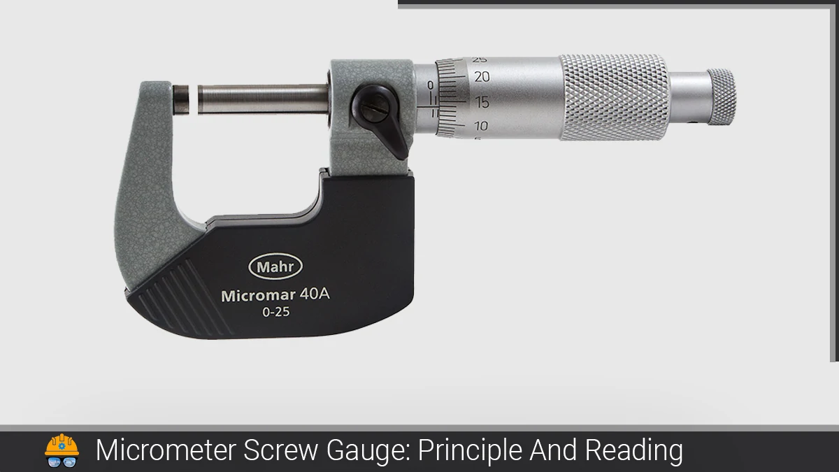
- Glass arc Theodolite: In this type of theodolite, micrometres are provided for reading horizontal and vertical graduated circles.
Theodolite Surveying
Theodolite surveying is a branch of surveying which is carried out by using an instrument called Theodolite. The instrument is known for its precision in measuring horizontal and vertical angles.
Technical Terms Related to Theodolite Surveying
The following are the technical terms used during the Theodolite surveying by the surveyor
- Horizontal Axis: The axis about which the telescope along with the vertical circle of a theodolite can be rotated in the vertical plane is called the horizontal axes/trunnion axis or transverse axis.
- Axis of the level tube: The straight line which is tangential to the longitudinal curve of the level tube at its centre is called the axis of the level tube.
- Centring: The process of setting up a theodolite exactly over the ground station mark is known as centring,
- Transiting: The process of turning the telescope in a vertical plane through 180 degrees about its horizontal axis is known as transiting.
- Swing: The continuous motion of the telescope about the vertical axis in the horizontal plane is called swing. When the telescope is rotated in a clockwise direction, it is known as the right swing. If it rotated in an anticlockwise direction it is known as a left swing.
- Face left Observation: When the vertical circle is on the left of the telescope at the time of observations, the observations of angle are known as face left observation.
- Face Right Observation: When the vertical circle is on the right of a telescope at the time of observations, the observations of angle are known as face right observation.
- Changing face: It is the operation of changing the face of the telescope from left to right and vice versa.
- Telescope Normal: Telescope is said to be normal when its vertical circle is to its left and the bubble of the telescope is up.
- Telescope Inverted: A telescope is said to be inverted or reversed when its vertical circle to its right and the bubble of the telescope is down.
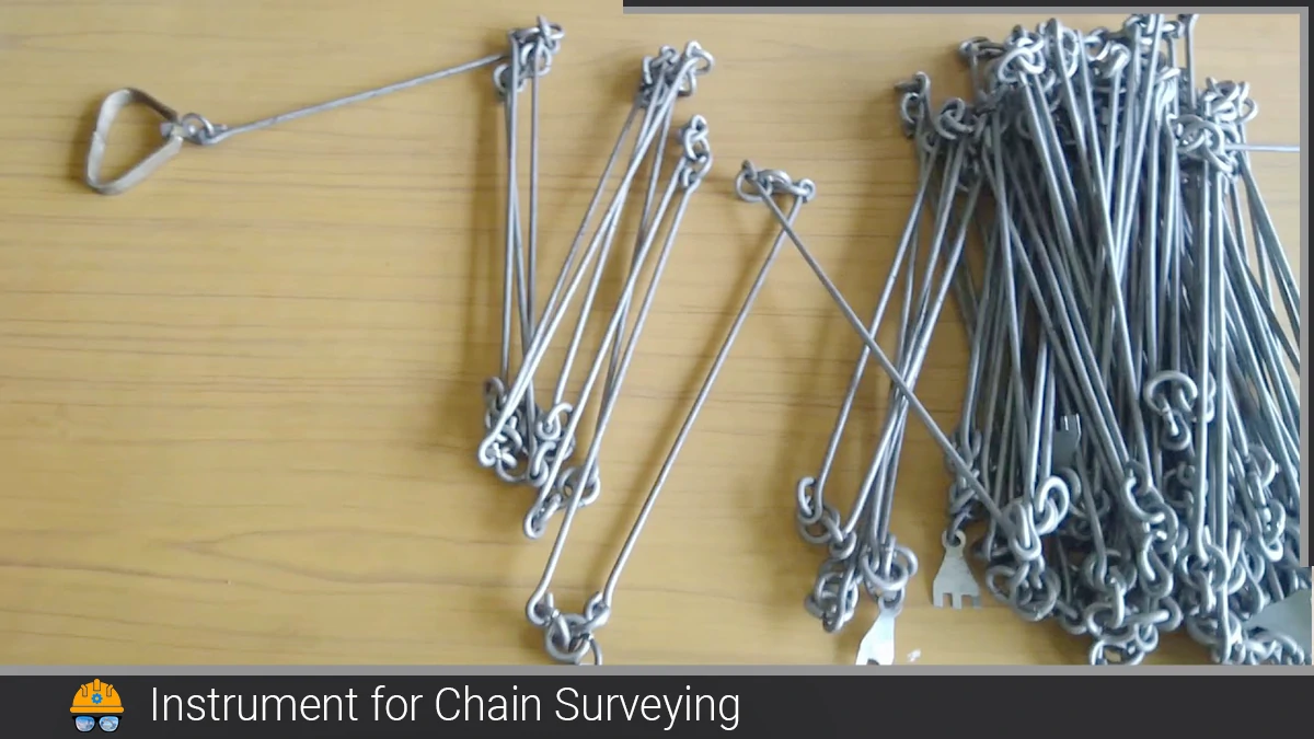
Also, read: What is Chain Surveying?: The instrument for Chain surveying
Adjustments of a Theodolite
There are two types of adjustments which are the same as in the level Instrument.
- Temporary adjustment
- Permanent adjustment
1. Temporary Adjustments of a Theodolite
Temporary adjustments are the operations carried out whenever a theodolite is set up at a new survey station. They ensure that the instrument is stable, correctly positioned and ready for accurate observations.
The temporary adjustments are performed in the following sequence:
1.1. Setting up the theodolite
Securely mount the theodolite on the tripod and place it approximately over the station mark. The tripod should be stable, with its legs firmly pressed into the ground.
1.2. Centring
Position the vertical axis of the theodolite exactly over the station mark using a plumb bob or optical plummet.
1.3. Levelling
Adjust the foot screws until the plate bubble is centred. This makes the vertical axis of the instrument truly vertical.
1.4. Eliminating parallax
Parallax occurs when the image of the target formed by the objective lens does not lie in the same plane as the crosshairs. When the observer’s eye is moved, the target image appears to move relative to the crosshairs. This apparent movement is called parallax and may cause inaccurate readings. Parallax is eliminated by the following two steps:
Focusing the eyepiece: Rotate the eyepiece until the crosshairs appear sharp and distinct.
Focusing the objective lens: Sight the target and adjust the focusing screw until the target image appears clear and sharp.
To check whether parallax has been eliminated, move the eye slightly from side to side. If the target image and crosshairs do not move relative to each other, parallax has been eliminated.
After these adjustments, the theodolite must be stable, accurately centred over the station mark and properly levelled before taking any readings. The phrase “setting up the level” should be replaced throughout the article with “setting up the theodolite.” NOAA also describes the instrument as being mounted on a stable tripod and carefully plumbed over the survey station.

You might also read: Dumpy level: its Principal & Components, also Application
Procedure for focusing the eyepiece:
- Direct the telescope either towards the sky or hold a sheet of white paper in front of the objective.
- Move the eyepiece in or out till the crosshairs appear distinct.
Procedure for focusing on the objective:
- Direct the telescope towards the levelling staff
- Turn the focusing screw till the image appears clear and sharp
- The image so formed must be in the plane of the crosshairs.
2. Permanent Adjustments of a Theodolite
Permanent adjustments are made occasionally to establish or restore the correct geometric relationships between the fundamental axes of a theodolite. They are different from temporary adjustments, which are carried out every time the instrument is set up.
The term permanent does not mean that the adjustment never needs to be repeated. Wear, mishandling, vibration, transportation or accidental damage may disturb these relationships and produce systematic errors in observations.
The main fundamental relationships are as follows.
| Permanent adjustment | Required geometric condition | Purpose |
|---|---|---|
| Plate-level adjustment | The axis of the plate level must be perpendicular to the vertical axis. | Ensures that the vertical axis becomes truly vertical when the bubble is centred. |
| Collimation or line-of-sight adjustment | The line of collimation must be perpendicular to the horizontal or trunnion axis. | Ensures accurate sighting and prevents collimation error. |
| Horizontal-axis adjustment | The horizontal or trunnion axis must be perpendicular to the vertical axis. | Ensures that the telescope rotates in a truly vertical plane. |
| Altitude-level adjustment | The axis of the altitude level must be parallel to the line of collimation. | Ensures that the line of sight is horizontal when the altitude bubble is centred. |
| Vertical-circle index adjustment | The vertical circle must show its reference reading when the line of collimation is horizontal. | Removes index error from vertical-angle measurements. |
★ Classification note: Textbooks do not always classify permanent adjustments in exactly the same way. Some list the altitude-level adjustment and vertical-circle index adjustment separately, while others combine them under the heading “adjustment of the altitude bubble and vertical index frame.” In this article, these conditions are explained separately for clarity. The vague term “adjustment of the telescope” should be replaced with “collimation adjustment” or “altitude-level and vertical-index adjustment.”
2.1. Plate-Level Adjustment
The axes of the plate levels must be perpendicular to the vertical axis of the theodolite. When the plate bubbles are centred, the vertical axis should therefore be truly vertical. If this relationship is disturbed, centring the bubble with the foot screws will not make the vertical axis genuinely vertical, resulting in errors in horizontal and vertical angle measurements.
2.2. Collimation or Line-of-Sight Adjustment
The line of collimation is the line passing through the intersection of the crosshairs and the optical centre of the objective lens. It must be perpendicular to the horizontal or trunnion axis.
If this condition is not satisfied, the line of sight will not be correctly aligned when the telescope is rotated or transited. This produces collimation error and affects the accuracy of measured angles. Crosshair or reticle adjustment is often included under this adjustment.
2.3. Horizontal-Axis Adjustment
The horizontal or trunnion axis must be perpendicular to the vertical axis. When the vertical axis is truly vertical, this condition makes the trunnion axis truly horizontal.
If the horizontal axis is inclined, the telescope will rotate in an inclined plane instead of a vertical plane. This can cause errors in vertical-angle measurements and may also affect horizontal directions.
2.4. Altitude-Level Adjustment
The axis of the altitude or telescope level must be parallel to the line of collimation. Therefore, when the altitude bubble is centred, the line of sight should be truly horizontal.
If this relationship is incorrect, the telescope may appear level while the line of sight is still inclined, causing errors in vertical angles and differences in elevation.
2.5. Vertical-Circle Index Adjustment
When the line of collimation is horizontal, the vertical circle should show its correct reference reading. This is normally 0° for a vertical-angle system, although some instruments use 90° for a zenith-angle system.
If the circle does not show the correct reference reading, the instrument has a vertical index error. This error may be corrected by adjusting the vertical index mechanism or by applying an index correction to the observed vertical angles.
Errors in Theodolite Surveying
Errors are differences between the observed value and the true value of a measured quantity. In theodolite surveying, errors are commonly classified as instrumental, personal and natural errors.
The sources of error in theodolite surveying are identified as follows: –
| Type of error | Common examples |
|---|---|
| Instrumental errors | Collimation, horizontal-axis, vertical-index, plate-level, eccentricity and graduation errors |
| Personal errors | Inaccurate centring, poor bisection, parallax, incorrect reading and recording |
| Natural errors | Temperature effects, atmospheric refraction, wind vibration and tripod settlement |
1. Instrumental Errors
Instrumental errors are caused by defects, maladjustment or wear in the theodolite.
- Collimation error: The line of collimation is not perpendicular to the horizontal or trunnion axis.
- Horizontal-axis error: The horizontal axis is not perpendicular to the vertical axis, causing the telescope to rotate in an inclined rather than a truly vertical plane.
- Vertical-index error: The vertical circle does not show its correct reference reading when the line of collimation is horizontal.
- Plate-level error: The plate-level axis is not perpendicular to the vertical axis, so centring the bubble does not make the vertical axis truly vertical.
- Eccentricity error: The centre of a graduated circle does not coincide with the instrument’s axis of rotation.
- Graduation error: The divisions on the horizontal or vertical circle are not perfectly equal.
Permanent adjustment, calibration and observations on both face-left and face-right positions help reduce the effect of many instrumental errors.
2. Personal Errors
Personal errors are caused by the observer. They may result from inaccurate centring or levelling, imperfect bisection of the target, failure to eliminate parallax, incorrect reading of the vernier, or mistakes in recording and calculating angles.
Parallax occurs when the target image and crosshairs do not lie in the same plane. It is eliminated by correctly focusing the eyepiece and objective lens. The ranging rod or target should also be held vertically and clearly bisected.
3. Natural Errors
Natural errors are caused by environmental conditions. Unequal atmospheric temperature may cause differential expansion or distortion of instrument components and may affect the stability of observations. Atmospheric refraction caused by temperature and air-density gradients may bend or deflect the line of sight, particularly over long distances or near the ground. Wind may vibrate the tripod, telescope or target, while soft or unstable ground may cause tripod settlement after the instrument has been levelled.
Methods of Reducing Theodolite Errors
The following practices help reduce errors:
- Perform permanent adjustments and periodic instrument checks.
- Carry out centring, levelling and parallax elimination carefully.
- Observe important angles in both face-left and face-right positions and use the mean value.
- Use the repetition method for measuring an important single angle.
- Use the reiteration method for measuring several angles around one station and check the angular closure.
- Keep backsight and foresight distances approximately equal where possible, especially during vertical-angle or trigonometric-levelling work.
- Set the tripod firmly on stable ground and recheck the bubble before and after observations.
- Avoid observations during strong wind, heat shimmer, fog or poor visibility.
- Read both verniers where applicable and record observations immediately.
Also, read: Plane Table Surveying: Advantages And Disadvantages
FAQs
Q: What is a Theodolite?

A Theodolite is an optical instrument used for measuring horizontal and vertical angles and also horizontal and vertical distances between two designated stations. It is a precision surveying instrument used mainly for measuring horizontal and vertical angles. The instrument is also precise for laying horizontal angles, locating points in line, prolonging survey lines, establishing grades, determining differences in elevation, setting out curves, etc.
Q: What is Theodolite surveying?
Theodolite surveying is a branch of surveying which is carried out by using an instrument called Theodolite. The instrument is known for its precision in measuring horizontal and vertical angles.
Q: What is a Transit Theodolite?
Transit Theodolites are those instruments that the telescope can transit (i.e. Telescope can revolve through a complete revolution about its horizontal axes in vertical planes) is called transit theodolite.
Q: Why theodolite cannot measure the distance?
A conventional theodolite cannot directly measure distance because it is designed to measure angles, not length. It contains:
1. A horizontal graduated circle for measuring horizontal angles;
2. A vertical graduated circle for measuring vertical angles; and
3. A telescope and crosshairs for sighting a target
References & Standards
- National Geodetic Survey. (n.d.). Theodolite. National Oceanic and Atmospheric Administration. View source
- U.S. Geological Survey. (2020). Procedures and Best Practices for Trigonometric Levelling in the U.S. Geological Survey. View source
- National Oceanic and Atmospheric Administration. (1982). Corrections Applied by the National Geodetic Survey to Precise Levelling Observations. NOAA Technical Memorandum NOS NGS 34. View source
- NPTEL. (n.d.). Introduction to Surveying and Mapping: Theodolite Surveying. IIT Roorkee. View course
- SRM Valliammai Engineering College. (n.d.). Surveying and Levelling Laboratory Manual. View PDF